

Circuit Simulation of GJB151B CS115 Part І: The analysis of calibration equipment indicators
-
摘要: GJB151B CS115给出了开展脉冲传导敏感度试验的校准平台构成和校准波形标准,但未明确校准平台各设备(脉冲源、电流注入环、校准夹具等)的具体指标需求。为解决这一问题,本文在前期脉冲电流注入电路仿真研究工作的基础上,构建了校准平台的时域电路模型,通过逐一改变模型参数的方法,仿真分析了脉冲源内部回路电感、电流注入环等效电感/电阻/电容等对校准波形前沿、半宽以及平顶降的影响,得出了平台各设备应达到的技术指标。该工作是对GJB151B CS115的有益补充,为搭建CS115试验平台,开展电子设备脉冲传导敏感度试验提供了技术支撑。Abstract: The composition and waveform of the calibration platform were defined in GJB151B CS115 for pulsed conducted sensitivity test, but the specific requirements for each device (pulse generator, current injection probe, calibration clamp, etc.) in the calibration platform are still not clear. To solve this problem, a time domain circuit model of the calibration platform was developed according the previous research on circuit simulation of pulsed current injection. By adjusting the parameters respectively, influences on the rise time and fall time of the calibration waveform caused by the inner inductance of the pulse generator and equivalent elements of the injection probe are simulated. Finally, the technical indicators for each device in the platform are obtained. This work is an essential supplement to GJB151B CS115 and is helpful to set up CS115 test platform for conducted immunity of electronic equipment test.
-
Key words:
- electromagnetic pulse /
- CS115 /
- conducted immunity /
- current injection
-
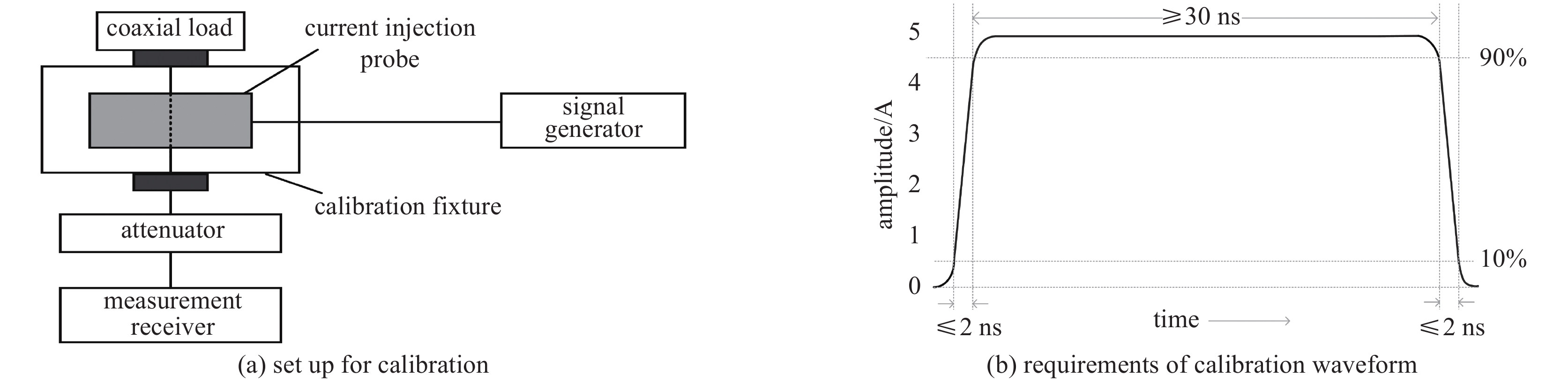
图 1 CS115校准设置及波形指标要求
Figure 1. Requirements of calibration setup and waveform in CS115
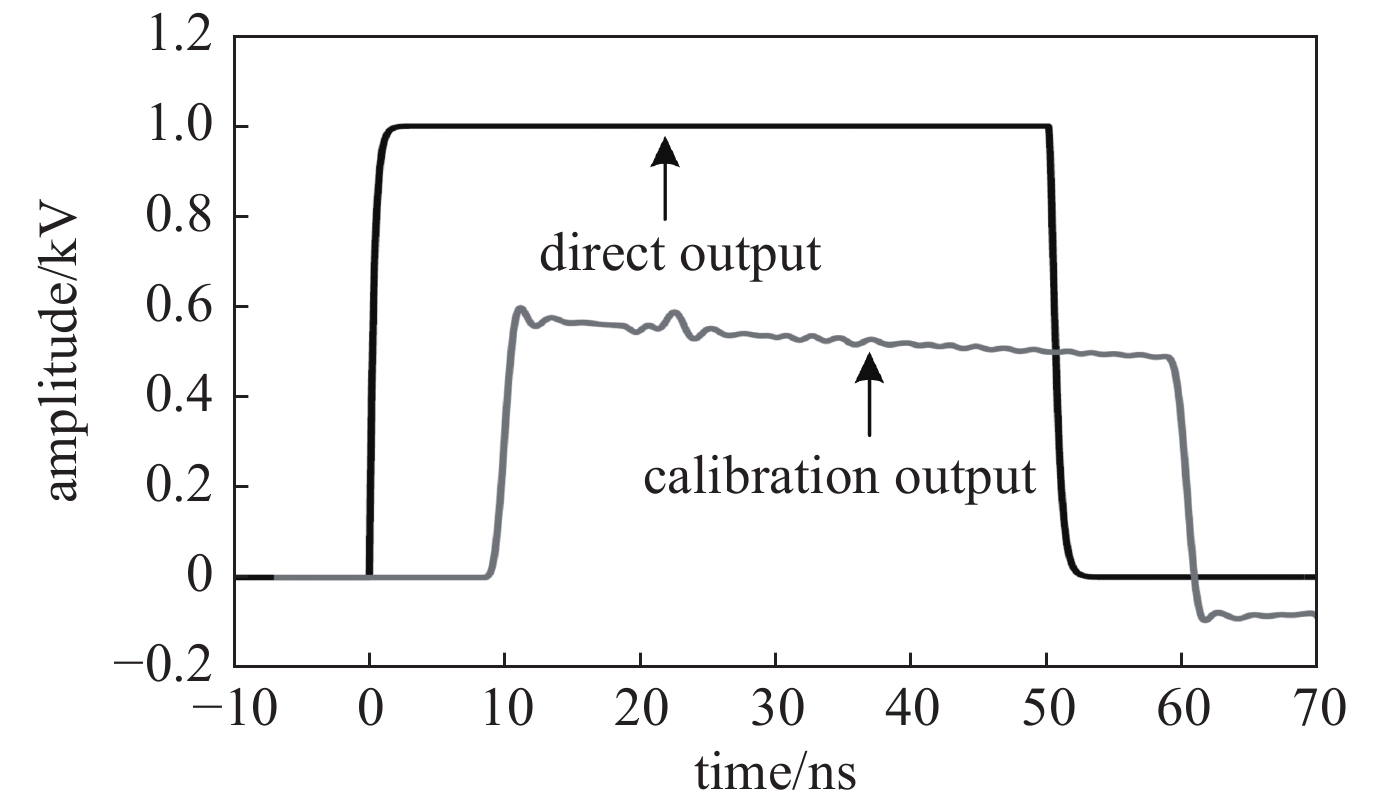
图 4 参考设置下脉冲源直接输出电压与校准耦合电压仿真波形
Figure 4. Direct output and calibration waveform under reference setup in simulation
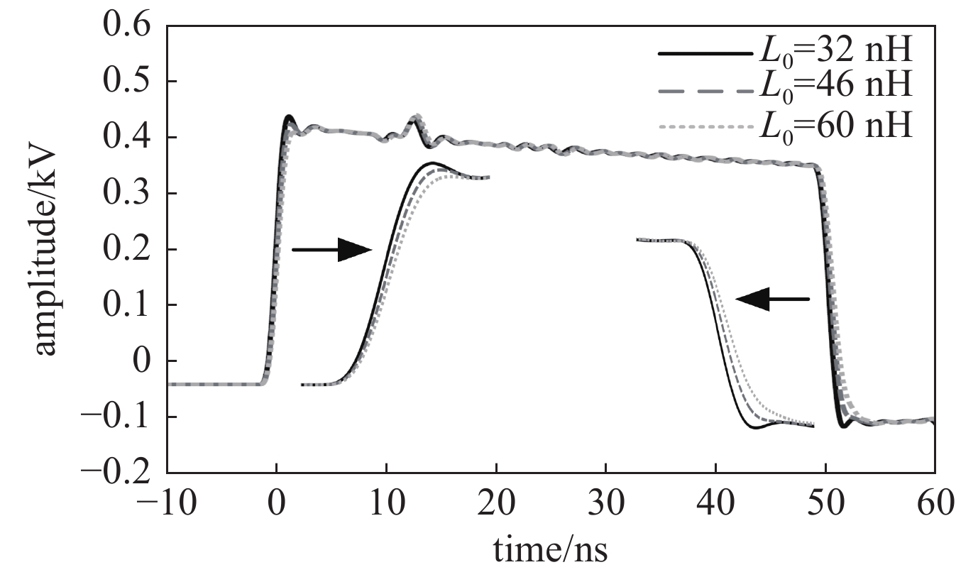
图 5 脉冲源不同电感L0下的校准电压仿真波形
Figure 5. Simulated calibration waveform with different L0 of pulsed current source

图 8 不同Lf 和Cf下的校准电压仿真波形
Figure 8. Simulated calibration waveforms with different Lf and Cf
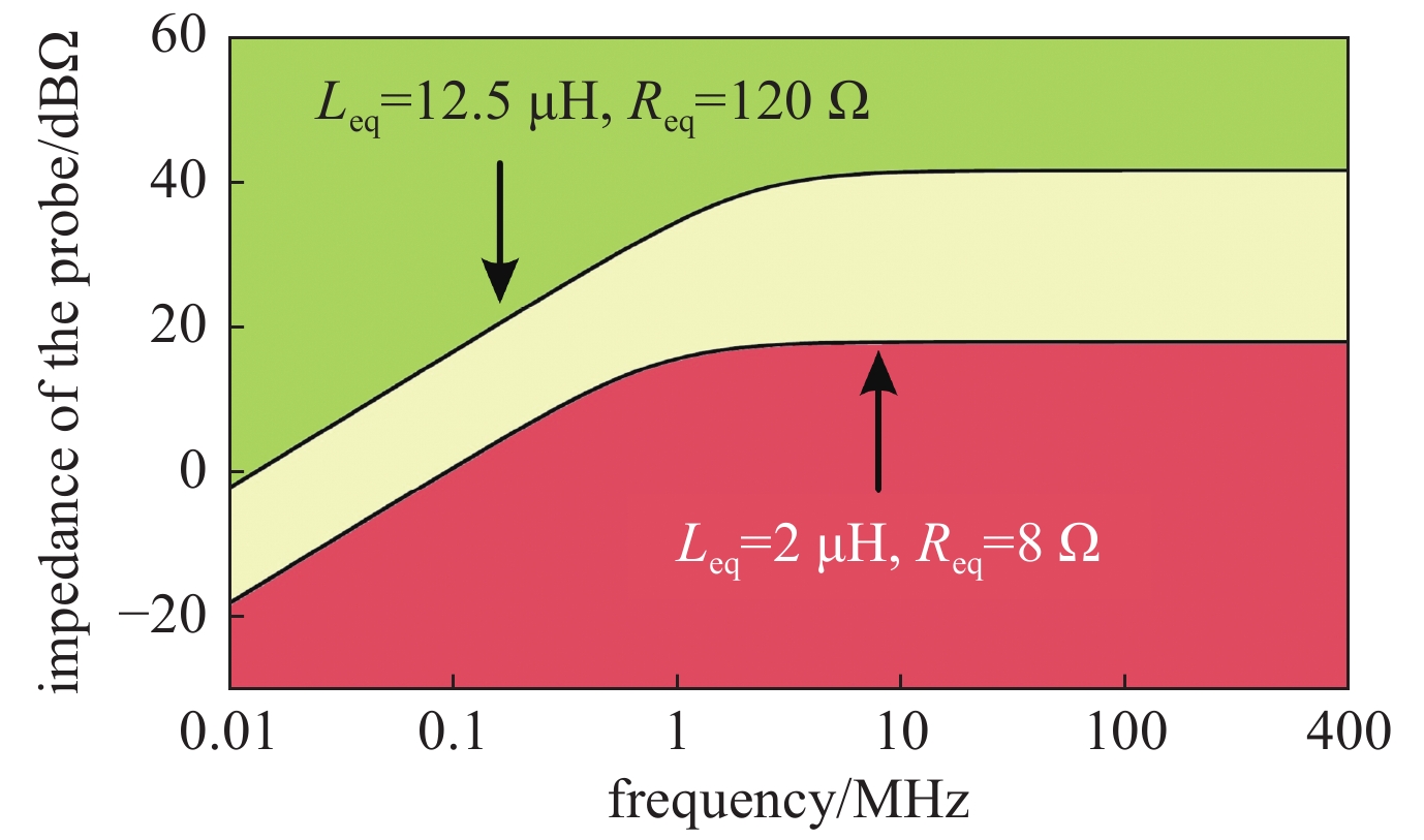
图 9 按照磁芯阻抗估算的电流注入环指标区间
Figure 9. Regions of current injection probe indicators according to the ferrite-core impedance
表 1 不同L0、Leq、Req下的校准波形输出指标
Table 1. Indicators of calibration waveform with different L0 , Leq and Req
rise time/ns fall time/ns VRE/kV VFE/kV FDR/% impulse generator output with 50 Ω load 0.7 1.1 1 1 0 L0=32 nH, Req=216 Ω, Leq=17.5 μH 1.2 1.4 0.59 0.49 17 inductance of
the generatorL0=46 nH 1.3 1.7 0.58 0.49 16 L0=60 nH 1.5 2.1 0.56 0.49 13 Req of the injection
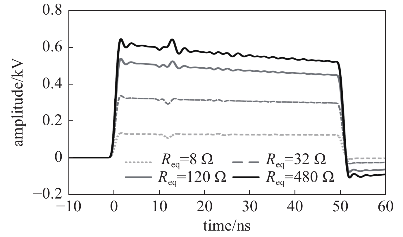
probe modelReq=8 Ω 1.3 1.5 0.13 0.12 8 Req=32 Ω 1.3 1.5 0.34 0.30 12 Req=120 Ω 1.2 1.4 0.54 0.46 15 Req=480 Ω 1.2 1.4 0.64 0.53 17 Leq of the injection
probe modelLeq=2 μH 1.2 1.4 0.59 0.27 54 Leq=5 μH 1.2 1.4 0.59 0.40 32 Leq=12.5 μH 1.2 1.4 0.59 0.47 20 Leq=30 μH 1.2 1.4 0.59 0.51 14  下载: 导出CSV
表 2 不同Req、 Ceq的校准波形上升时间tr和下降时间tp
Table 2. The rise time and fall time of calibration waveform with different Req and Ceq
Ceq=10 pF Ceq=20 pF Ceq=30 pF Ceq=40 pF Ceq=50 pF tr/ns tp/ns tr/ns tp/ns tr/ns tp/ns tr/ns tp/ns tr/ns tp/ns Req=8 Ω 1.3 1.4 1.3 1.5 1.3 1.5 1.4 1.6 1.4 1.6 Req=32 Ω 1.2 1.4 1.3 1.5 1.4 1.6 1.6 1.8 1.8 2.0 Req=120 Ω 1.2 1.4 1.3 1.5 1.6 1.8 1.9 2.2 2.4 2.6 Req=216 Ω 1.1 1.3 1.4 1.5 1.7 1.9 2.1 2.3 2.6 2.9 Req=400 Ω 1.0 1.3 1.4 1.5 1.7 1.9 2.2 2.4 2.8 3.0
下载: 导出CSV
-
[1] GJB151B-2013, 军用设备和分系统电磁发射和敏感度要求与测量[S]GJB151B-2013, 军用设备和分系统电磁发射和敏感度要求与测量[S]. (GJB151B-2013, Electromagnetic emission and susceptibility requirements and measurements for military equipment and subsystems[S] [2] 黄华, 陈量. 信息系统装备电磁兼容性设计技术及工程实践[J]. 微波学报, 2018, 34(7):483-486. (Huang Hua, Chen Liang. EMC design technology and engineering of information system equipment[J]. Journal of Microwaves, 2018, 34(7): 483-486 [3] 曹斌, 蔡明娟. GJB151B与GJB151A对舰船装备电磁兼容性要求的对比分析[J]. 船舶, 2017, 28(3):72-78. (Cao Bin, Cai Mingjuan. Comparison analysis of electromagnetic compatibility requirements of ship equipment between GJB 151B and GJB 151A[J]. Ship & Boats, 2017, 28(3): 72-78 [4] 钟辉. 某机载设备电磁兼容性改进设计[J]. 安全与电磁兼容, 2018, 2:80-84. (Zhong Hui. The improved design of EMC for an airborne equipment[J]. SAFETY & EMC, 2018, 2: 80-84 [5] MIL-STD-461E, Requirements for the control of electromagnetic interference characteristics of subsystems and equipment[S]. [6] 董佳, 姚利军, 余璨译. 一种CS115/CS116电流监测探头时域校准夹具的设计[J]. 宇航技测技术, 2017, 37(5):35-39. (Dong Jia, Yao Lijun, Yu Canyi. Design of calibration-jig using in CS115/CS116 current monitor probe time-domain calibration[J]. Journal of Astronautic Metrology and Measurement, 2017, 37(5): 35-39 [7] 徐亮, 胥明. GJB151B传导敏感度测试要求的分析[J]. 微波学报, 2016 (S2): 3 441-443Xu Liang, Xu Ming. Analysis of conducted susceptibility requirement for GJB151B[J]. Journal of Microwaves, 2016 (S2): 3: 441-443 [8] 林荣刚, 凤卫锋, 梁双港. 注入脉冲激励传导敏感度测试的不确定度评定[J]. 电子设计工程, 2013, 21(17):86-89. (Lin Ronggang, Feng Weifeng, Liang Shuanggang. Evaluation of uncertainty in test of conducted susceptibility of injection impulse excitation[J]. Electronic Design Engineering, 2013, 21(17): 86-89 doi: 10.3969/j.issn.1674-6236.2013.17.027 [9] Cui Z T, Grassi F, Pignari A S. Circuit modeling of the test setup for pulsed current injection[C]//Proceedings of 2016 IEEE 2012 Asia-Pacific Symposium on Electromagnetic Compatibility. 2016. [10] 崔志同, 毛从光, 孙蓓云. 感性脉冲电流注入装置的PSPICE电路建模[J]. 电子学报, 2017, 45(6):1513-1517. (Cui Zhitong, Mao Congguang, Sun Beiyun. SPICE modeling of pulsed current injection with inductive coupling[J]. Acta Electronica Sinica, 2017, 45(6): 1513-1517 doi: 10.3969/j.issn.0372-2112.2017.06.033 [11] Cui Z T, Wei B, Grassi F, Pignari A S. A pulsed current injection setup and procedure to reproduce intense transient electromagnetic disturbance[J]. IEEE Transactions on Electromagnetic Compatibility, 2018, 60(6): 2065-2068. doi: 10.1109/TEMC.2017.2789206 [12] Cui Z T, Wei B, Grassi F, Pignari A S. Experimental analysis and circuit modeling of pulsed current injection in wire pairs[C]//Proceedings of IEEE Symposium on Electromagnetic Compatibility. 2018. [13] 崔志同, 魏兵. 同轴电缆感性脉冲电流注入试验仿真方法[J]. 西安电子科技大学学报, 2021, 48(4):42-49. (Cui Zhitong, Wei Bing. Simulation methods for inductive pulsed current injection on coaxial cable[J]. Journal of Xidian University, 2021, 48(4): 42-49 [14] Lofon F, Belakhouy Y, Daran F. Injection probe modeling for bulk current injection test on multiconductor transmission lines[C]//Proceedings of IEEE Symposium on Embedded Electromagnetic Compatibility. 2007. [15] 崔志同. HEMP脉冲电流注入的仿真与实验研究[D]. 西安: 西安电子科技大学, 2020Cui Zhitong. Simulation and experimental research on HEMP pulsed current injection[D]. Xi’An: Xidian University, 2020 -


 点击查看大图
计量
- 文章访问数: 1495
- HTML全文浏览量: 465
- PDF下载量: 57
- 被引次数: 0
