

Application of vibration wire measurement technology to pre-alignment units of High Energy Photon Source booster
-
摘要: 高能同步辐射光源(HEPS)的预准直单元数量庞大,且磁铁准直精度要求极高,为检验HEPS增强器预准直单元磁铁准直精度,需要在实验厅按照一定比例对其进行振动线磁中心验证测量。基于预研阶段已研发的振动线系统,详细介绍了振动线磁中心测量原理及扫描方法,研究了HEPS增强器两铁单元的磁中心准直精度检测方法并进行了验证实验。设计并搭建了振动线高精度重复定位夹持机构装置,研究了振动线下垂量的修正方法,并对增强器两铁单元的磁中心扫描结果进行拟合分析。实验结果表明,HEPS增强器两铁单元满足磁铁间相对位置误差优于 50 μm的预准直精度要求。Abstract: The pre-alignment units of the High Energy Photon Source (HEPS) are numerious and require extremely high precision in magnet alignment. To verify the magnetic alignment accuracy of the pre-alignment magnet unit in the HEPS booster, vibration wire magnetic center verification measurements need to be carried out in the experimental hall at a certain ratio. Based on the vibration wire system developed in the pre-research stage, a detailed study is conducted to introduce the measurement principle and scanning method of the vibration wire magnetic center. The research focuses on the magnetic center allignment accuracy detection method of the two magnet units in the HEPS booster and conducts verification experiments. A high-precision repeat positioning clamping mechanism for the vibration wire was designed and constructed, and a method for correcting the sag of the vibration wire was studied. The magnetic center scan results of the two magnet units in the booster were analyzed by fitting. The experimental results show that the pre-alignment accuracy requirement of the HEPS booster for a relative position error between magnets better than 50 μm is satisfied. This study provides a reference for accurate measurement of the vibration wire magnetic center in other accelerator pre-allignment magnet units.
-
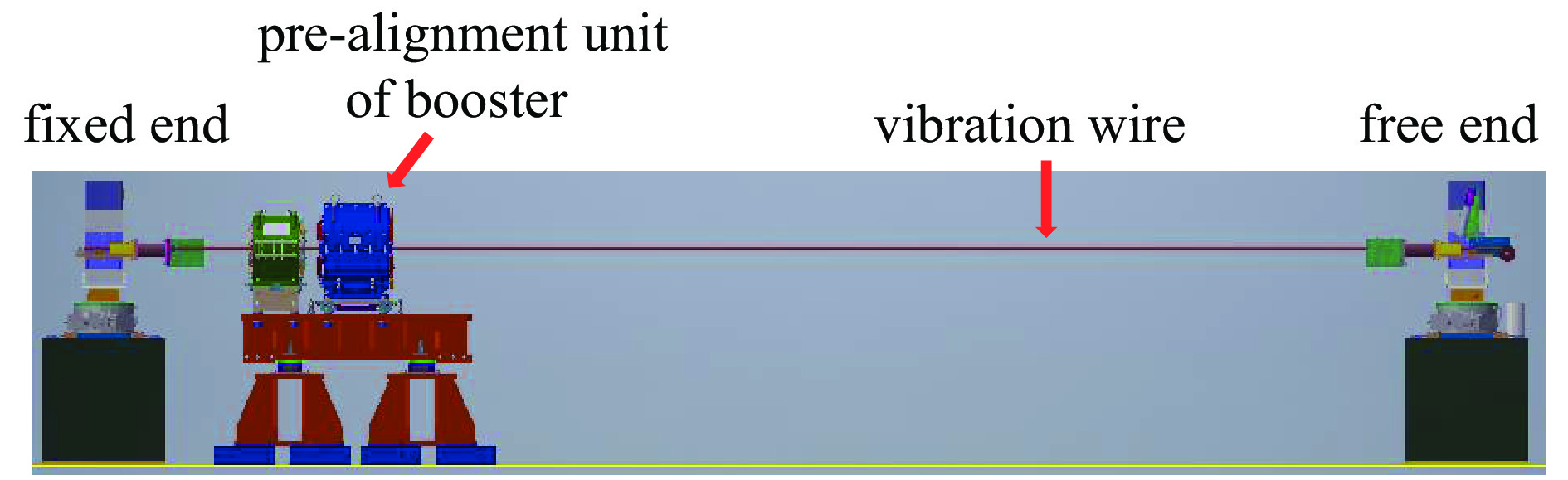
图 2 增强器预准直单元振动线磁中心测量系统
Figure 2. Vibration wire magnetic center measurement system of pre-alignment unit of booster

图 3 四极磁铁水平和垂直磁中心测量方法示意图
Figure 3. Schematic diagram of measuring methods for horizontal and vertical magnetic centers of quadrupole magnets
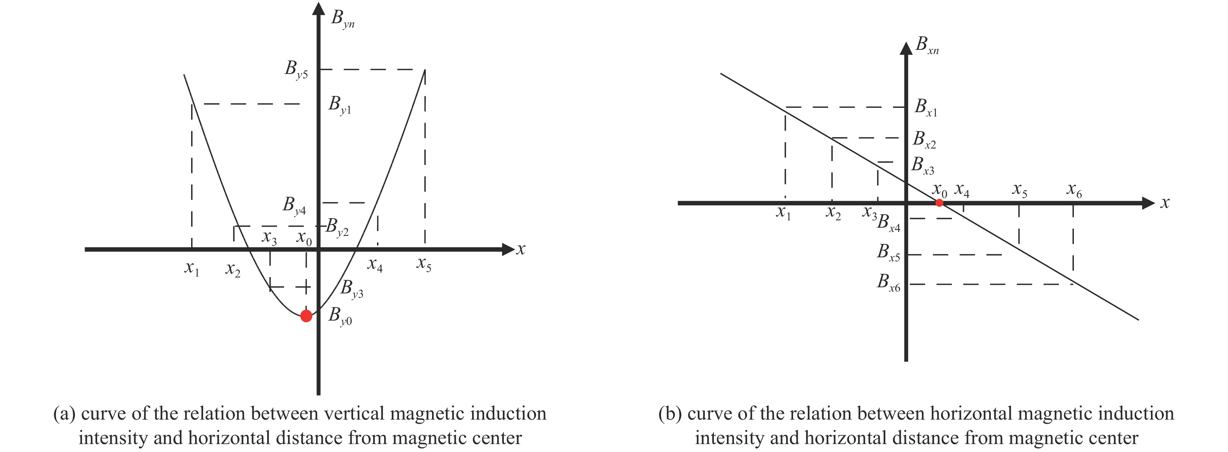
图 4 六极磁铁水平磁中心测量方法示意图
Figure 4. Schematic diagram of measuring method of horizontal magnetic center of sextupole magnet
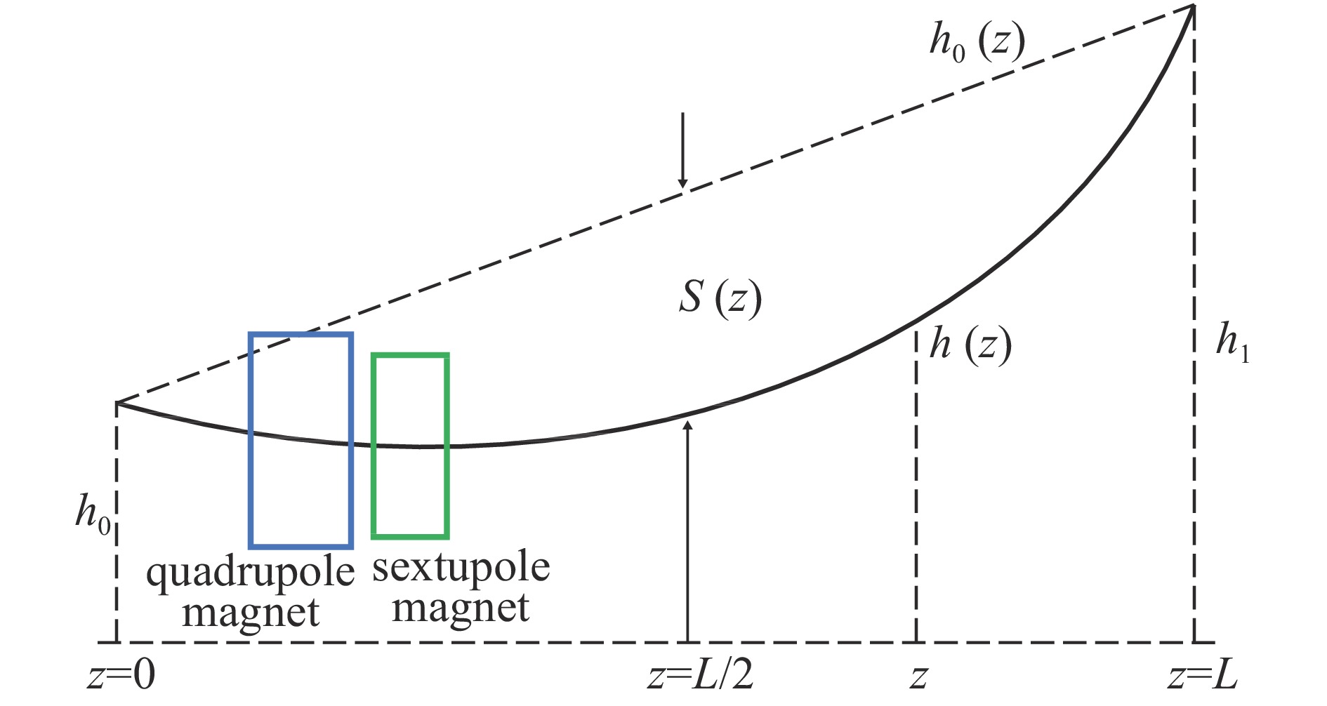
图 8 振动线磁中心扫描简意图
Figure 8. Simplified schematic of magnetic center scan of vibrating wire
表 1 四六极铁设计参数
Table 1. Design parameters of the quadrupole and sextupole magnets
magnet max.
fieldmin.
field
aperture
/mmmagnetic
length
/mmcore
length
/mturns per
polemax. of
current
/Amin. of
current
/Agood field
region
/mmfield
errorsmax.
of power
loss
/kWwater
pressure
drop
/(kg·cm−2)water flow
velocity
/(m·s−1)temperature
rise
/℃weight
/kgBS1QD13 33 T/m 1.5 T/m 40 300 290 13 411 19 ±16 5×10⁻⁴ 3 3 2.45 5.7 345 BS1SD6 1000 T/m2 30 T/m2 40 200 194 8 135.3 4.1 ±16 1×10⁻³ 0.33 3 1.89 3 75  下载: 导出CSV
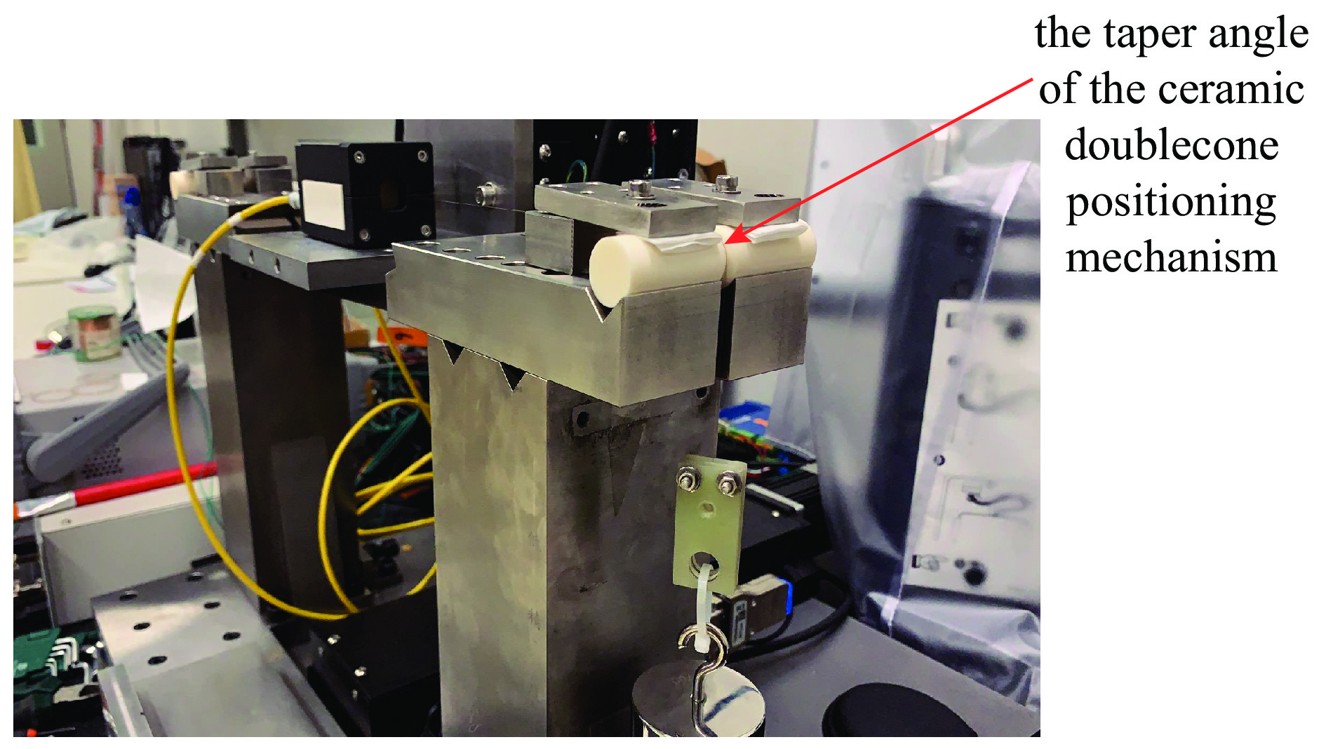
表 2 陶瓷双锥重复定位精度
Table 2. Ceramic double cone repeat positioning accuracy
vibrating wire repeated
positioning methodcone
angledeviation
Xmax/μmdeviation
Ymax/μmdeviation
Xmin/μmdeviation
Ymin/μmdeviation
Xsat/μmdeviation
Ysat/μmcompared with
previous time70° 8.3 4.4 0.1 0.2 2.7 1.3 90° 4.9 1.1 0.0 0.0 0.9 0.3 110° 5.9 4.9 0.0 0 1.4 1.4 compared with the
initial zero70° 18.9 3.0 0.0 1.1 6.4 0.6 90° 5.5 2.4 0.0 0.0 1.0 0.6 110° 6.0 6.4 0.0 0.1 1.6 1.9
下载: 导出CSV
表 3 振动线与预准直单元水平磁轴准直
Table 3. The vibrating wire is aligned on the horizontal magnetic axis of the pre-alignment unit
position operator lattice value horizontal offset/mm fixed end magnetic axis point 1 −50.0 −1.000 2 −50.0 −1.000 fixed end vibrating wire 1 −50.2 −1.004 2 −50.0 −1.000 free end magnetic axis point 1 −50.0 −1.000 2 −50.0 −1.000 free end vibrating wire 1 −50.2 −1.004 2 −50.3 −1.006
下载: 导出CSV
表 4 振动线与预准直单元垂直磁轴准直
Table 4. The vibrating wire is aligned on the vertical magnetic axis of the pre-alignment unit
position visual distance of the
instrument from each
measuring point/mmlattice
valuelattice value
deviationvertical
offset/mmvertical offset
deviation/mmlattice
valuelattice value
deviationvertical
offset/mmvertical offset
deviation/mmoperator 1 operator 2 vibrating wire of the fixed
end of the quadrupole
magnet2550 −41.0 50.0 −0.820 1.000 −41.5 51.0 −0.830 1.020 magnetic axis point of the
fixed end of the
quadrupole magnet2295 9.0 0.180 9.5 0.190 vibrating wire of the free
end of the sextupole
magnet2550 −43.0 50.0 −0.860 1.000 −43.0 50.5 −0.860 1.010 magnetic axis point of the
free end of the sextupole
magnet2305 7.0 0.140 7.5 0.150
下载: 导出CSV
表 5 预准直单元四六极磁铁位置的振动线下垂量
Table 5. Sag of vibration wire at the position of pre-alignment unit quadrupole and sextupole magnets
type of magnet L/mm δh/mm f1/Hz z1/mm z3/mm S(z)/mm quadrupole magnet 7453.0 1.8 18.36 1272.0 1592.0 −0.218 sextupole magnet 18.30 1713.0 1931.0 −0.236
下载: 导出CSV
表 6 预准直单元振动线磁中心扫描重复性
Table 6. Repeatability of vibrating-wire magnetic center scanning in pre-alignment unit
type of
magnettimes X/mm X deviation/mm Y/mm Y deviation/mm X/mm X deviation/mm Y/mm Y deviation/mm magnetic center of fixed end magnetic center of free end quadrupole
magnetthe first time −1.002 0.002 0.997 −0.002 −1.002 0.001 0.997 −0.003 the second time −1.000 0.995 −1.001 0.994 sextupole
magnetthe first time −0.959 −0.004 0.989 0.006 −0.965 −0.004 0.989 0.001 the second time −0.963 0.995 −0.969 0.990
下载: 导出CSV
表 7 高能光源增强器预准直单元振动线扫描三维磁中心拟合偏差
Table 7. Fit deviation of vibration line scanning of 3D magnetic center of the pre-alignment unit of the High Energy Photon Source booster
vibration wire fixation mode magnet inlet and outlet X/mm Y/mm Z/mm fixed end BS1QD13EN 0.003 −0.003 0.000 free end BS1QD13EX −0.017 0.010 320.000 fixed end BS1SD6EN 0.017 −0.007 441.000 free end BS1SD6EX −0.003 0.000 661.000
下载: 导出CSV
-
[1] 焦毅, 潘卫民. 高能同步辐射光源[J]. 强激光与粒子束, 2022, 34:104002 doi: 10.11884/HPLPB202234.220080Jiao Yi, Pan Weimin. High energy photon source[J]. High Power Laser and Particle Beams, 2022, 34: 104002 doi: 10.11884/HPLPB202234.220080 [2] Jiao Yi, Xu Gang, Cui Xiaohao, et al. The HEPS project[J]. Journal of Synchrotron Radiation, 2018, 25(6): 1611-1618. doi: 10.1107/S1600577518012110 [3] Jiao Yi, Chen Fusan, He Ping, et al. Modification and optimization of the storage ring lattice of the High Energy Photon Source[J]. Radiation Detection Technology and Methods, 2020, 4(4): 415-424. doi: 10.1007/s41605-020-00189-7 [4] Meng Cai, He Xiang, Jiao Yi, et al. Physics design of the HEPS LINAC[J]. Radiation Detection Technology and Methods, 2020, 4(4): 497-506. doi: 10.1007/s41605-020-00205-w [5] Guo Yuanyuan, Wei Yuanyuan, Peng Yuemei, et al. The transfer line design for the HEPS project[J]. Radiation Detection Technology and Methods, 2020, 4(4): 440-447. doi: 10.1007/s41605-020-00209-6 [6] 于成浩, 殷立新, 杜涵文, 等. 上海光源准直测量方案设计[J]. 强激光与粒子束, 2006, 18(7):1167-1172Yu Chenghao, Yin Lixin, Du Hanwen, et al. Survey and alignment design of Shanghai synchrotron radiation facility[J]. High Power Laser and Particle Beams, 2006, 18(7): 1167-1172 [7] Temnykh A, Levashov Y, Wolf Z. A study of undulator magnets characterization using the vibrating wire technique[J]. Nuclear Instruments and Methods in Physics Research Section A: Accelerators, Spectrometers, Detectors and Associated Equipment, 2010, 622(3): 650-656. [8] Kang Wen, Liu Lei, Yu Yongji, et al. Design of the magnets for the HEPS injector[J]. Radiation Detection Technology and Methods, 2022, 6(2): 143-149. doi: 10.1007/s41605-022-00314-8 [9] Peng Yuemei, Duan Zhe, Guo Yuanyuan, et al. Design of the HEPS booster lattice[J]. Radiation Detection Technology and Methods, 2020, 4(4): 425-432. doi: 10.1007/s41605-020-00202-z [10] 吴蕾. 振动线测量技术研究[D]. 北京: 中国科学院高能物理研究所, 2016Wu Lei. Research of vibrating wire measurement technique[D]. Beijing: Institute of High Energy Physics, Chinese Academy of Sciences, 2016 [11] Arpaia P, Buzio M, Perez J J G, et al. Magnetic field measurements on small magnets by vibrating wire systems[C]//2011 IEEE International Instrumentation and Measurement Technology Conference. 2011: 1-4. [12] Wolf Z. A vibrating wire system for quadrupole fiducialization[R]. Menlo Park: SLAC National Accelerator Laboratory, 2010. [13] Wu Lei, Li Chunhua, Wang Xiaolong, et al. Research development of high precision installation and alignment system for HEPS[C]//6th International Particle Accelerator Conference. 2015: 2924-2926. [14] 赵籍九, 尹兆升. 粒子加速器技术[M]. 北京: 高等教育出版社, 2006Zhao Jijiu, Yin Zhaosheng. Particle accelerator technology[M]. Beijing: Higher Education Press, 2006 [15] Fukami K, Azumi N, Inoue S, et al. Performance verification of a precise vibrating-wire magnet alignment technique for next-generation light sources[J]. Review of Scientific Instruments, 2019, 90: 054703. doi: 10.1063/1.5086505 [16] Jain A, Anerella M, Ganetis G, et al. Vibrating wire R&D for alignment of multipole magnets in NSLS-II[C]//10th International Workshop on Accelerator Alignment. 2008. [17] 闫路平, 董岚, 王铜, 等. 一种关于线的重复定位装置: 214843081U[P]. 2021-11-23Yan Luping, Dong Lan, Wang Tong, et al. A device for repeated positioning of wires: 214843081U[P]. 2021-11-23 [18] 闫路平, 董岚, 王铜, 等. 粒子加速器丝线位置测量电容传感器标定方法[J]. 强激光与粒子束, 2022, 34:114002 doi: 10.11884/HPLPB202234.220447Yan Luping, Dong Lan, Wang Tong, et al. Calibration method of capacitance sensor for particle accelerator wire position measurement[J]. High Power Laser and Particle Beams, 2022, 34: 114002 doi: 10.11884/HPLPB202234.220447 [19] Jain A. High precision alignment of multipoles[C]//Low Emittance Rings 2010 Workshop. 2010. [20] Jain A. Precision alignment of multipoles on a girder for NSLS-II[C]//17th International Magnetic Measurement Workshop. 2011. [21] 吴蕾, 王小龙, 李春华, 等. 振动线准直技术的原理和研究概述[J]. 强激光与粒子束, 2013, 25(10):2479-2486 doi: 10.3788/HPLPB20132510.2479Wu Lei, Wang Xiaolong, Li Chunhua, et al. Theory and research overview of vibrating wire technique[J]. High Power Laser and Particle Beams, 2013, 25(10): 2479-2486 doi: 10.3788/HPLPB20132510.2479 [22] Jain A, He Ping, Ganetis G. Measurement of wire sag in a vibrating wire setup[C]//15th International Magnet Measurement Workshop. 2007. [23] 王科, 杨治勇, 廖树清, 等. 脉冲紧线磁轴测量方法中金属丝下垂的影响分析[J]. 核技术, 2015, 38:080201 doi: 10.11889/j.0253-3219.2015.hjs.38.080201Wang Ke, Yang Zhiyong, Liao Shuqing, et al. Analysis of the wire sag in the pulsed taut-wire technique[J]. Nuclear Techniques, 2015, 38: 080201 doi: 10.11889/j.0253-3219.2015.hjs.38.080201 [24] Zhang C, Mitsuda C, Kajimoto K. Eigenfrequency wire alignment system for magnet fiducialization[C]//14th International Workshop on Accelerator Alignment. 2016. [25] Zhang C, Azumi N, Fukami K, et al. Magnet alignment monitoring system with eigenfrequency-based wire sag correction[J]. Measurement Science and Technology, 2021, 32: 075009. doi: 10.1088/1361-6501/abe5e4 -


 点击查看大图
计量
- 文章访问数: 462
- HTML全文浏览量: 185
- PDF下载量: 58
- 被引次数: 0
