

Design of insulation support system for 120 keV positive ion source accelerator
-
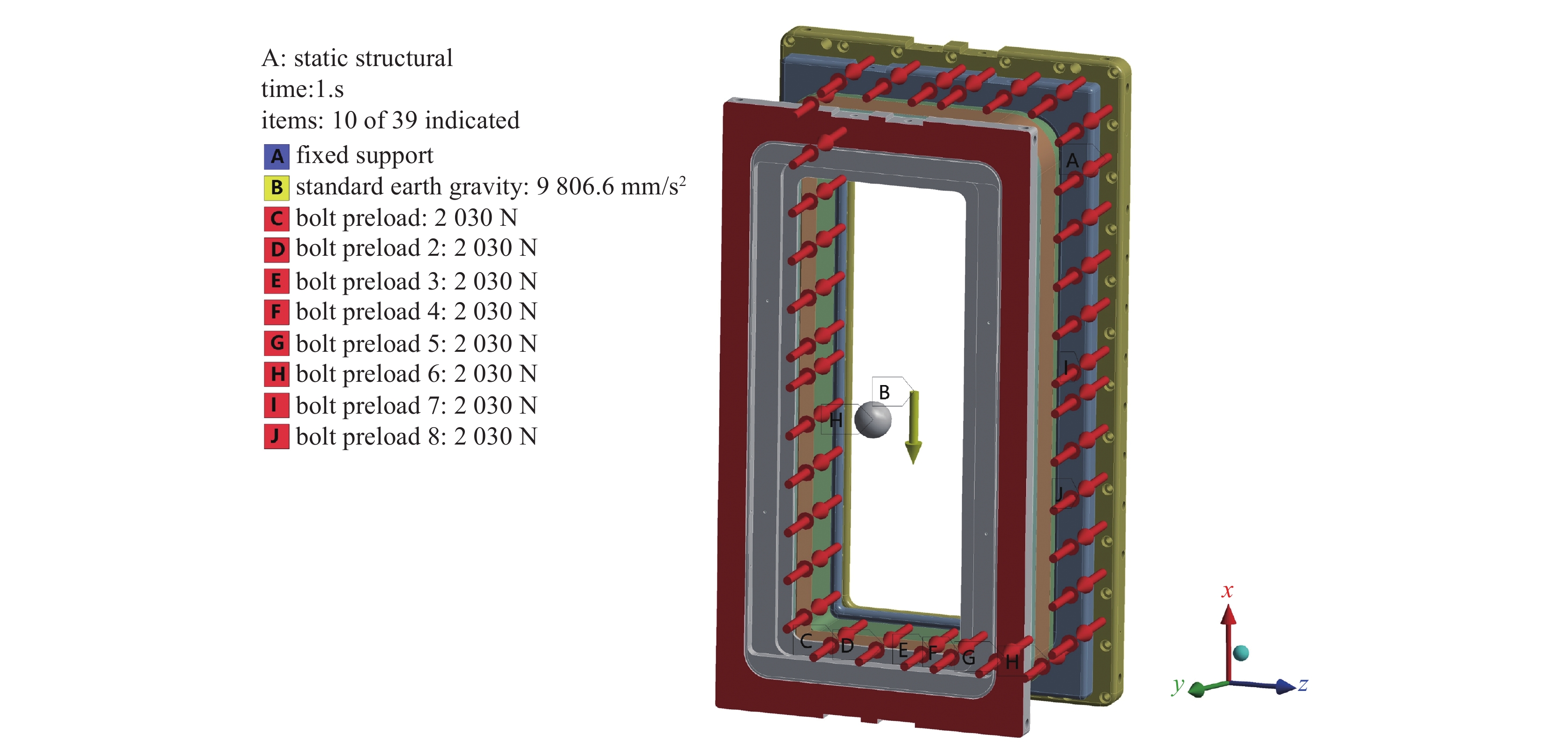
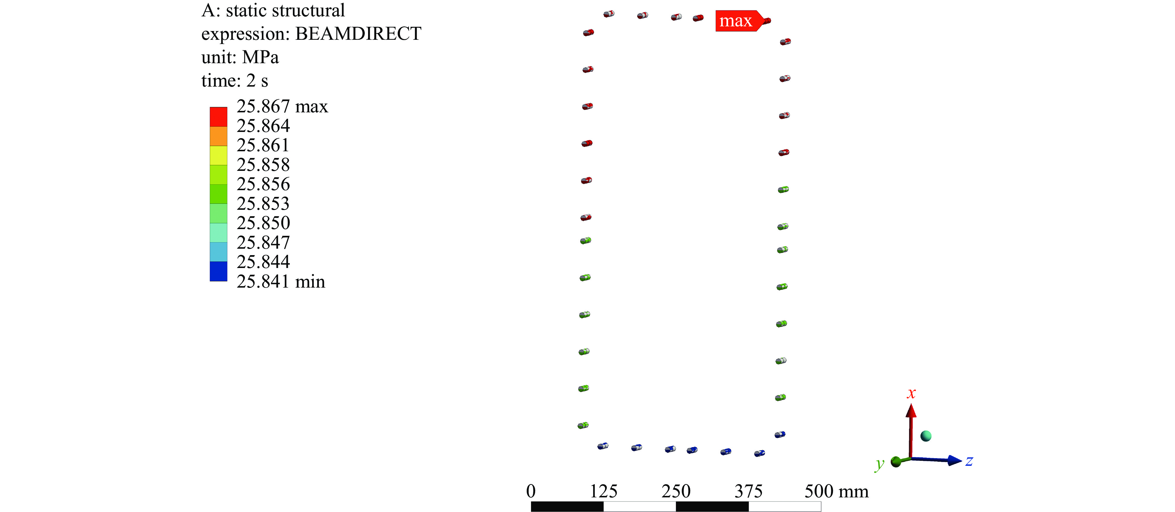
摘要: 针对120 keV正离子源,设计了加速器的绝缘支撑系统,确定了绝缘体与支撑法兰的连接方式及相关参数,并通过有限元分析的方法,针对电场集中和连接支撑的问题,开展了绝缘支撑系统的优化设计。分别对绝缘体和电极进行静电模拟,确定了绝缘体的材料及结构参数,研究了加速器的绝缘性能。研究表明各绝缘体周围最大电场值低于4 kV/mm,电极间最大电场值约为14 kV/mm,满足120 keV正离子源加速器耐压要求。其次考虑离子源的垂直安装,在离子源重力作用下EG支撑法兰和绝缘体的连接螺栓要承受很大的正应力和剪应力,开展了加速器的机械性能研究。经过力学分析,螺栓最大正应力为26.336 MPa,剪切力为1.292 MPa。经过模拟分析,螺栓最大正应力为25.867 MPa,与理论解相差1.78%,小于材料的抗拉强度;最大剪切力为1.295 MPa,与理论解相差0.23%,小于材料的抗剪强度。研究结果表明120 keV正离子源加速器机械性能满足设计要求。Abstract: For the 120 keV positive ion source, the insulation support system for the accelerator was designed, and the connection mode and basic parameters of the insulators and support flanges were determined. The optimization design of the insulation support system was studied through the finite element analysis method for the problems of electric field concentration and connection support. The electrostatic simulations of insulators and grid plates were carried out to determine the material and structural parameters of insulators, so as to study the insulating properties of the accelerator. The study shows that the maximum electric field around each insulator is less than 4 kV/mm, and the maximum electric field between grids is about 14 kV/mm, which can meet the voltage withstand requirements of 120 keV positive ion source accelerator. Secondly, considering the vertical installation of ion source, the connecting bolts of EG support flange and insulator would bear great normal stress and shear stress under the action of ion source gravity, thus the mechanical properties of the accelerator were studied. After mechanical analysis, the maximum normal stress of the bolt is 26.336 MPa, and the shear force is 1.292 MPa. The maximum normal stress of the bolt in the finite element analysis is 25.867 MPa, which is 1.78% different from the theoretical solution and less than the tensile strength of the material. The maximum shear force is 1.295 MPa, which is 0.23% different from the theoretical solution and less than the shear strength of the material. The results show that the mechanical properties of the 120 keV positive ion source accelerator meet the design requirements.
-
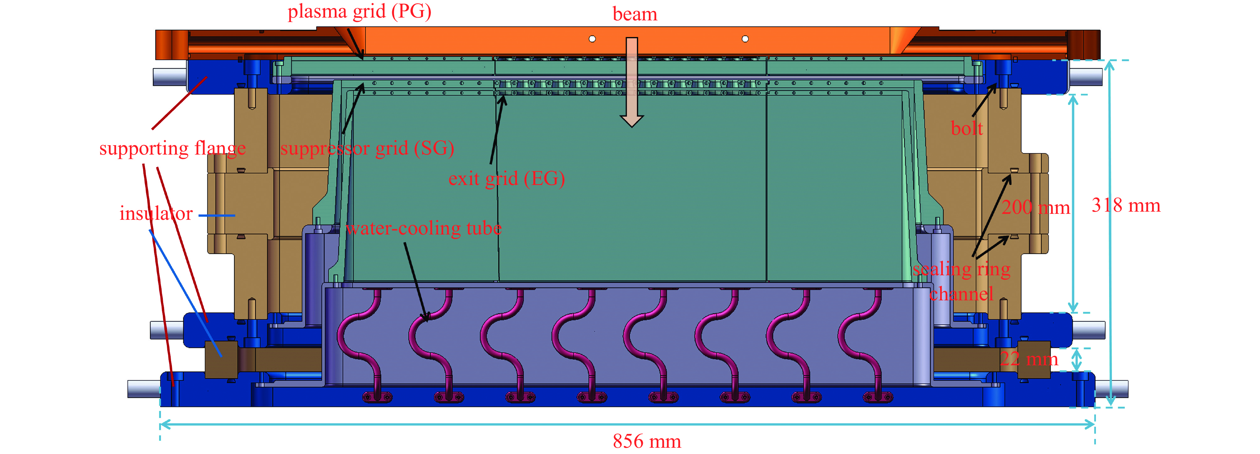
图 1 120 keV正离子源加速器剖面图
Figure 1. Schematic diagram of 120 keV positive ion source accelerator
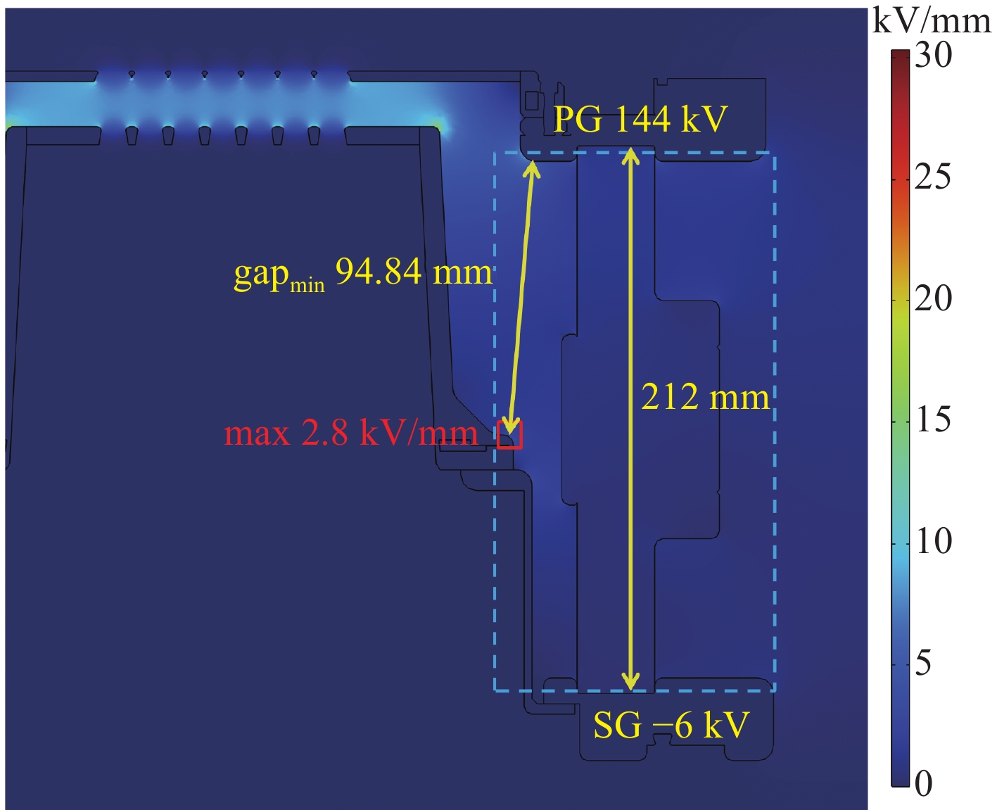
图 3 PG-SG绝缘体电场分布图
Figure 3. Distribution diagram of electric fields around PG-SG insulator
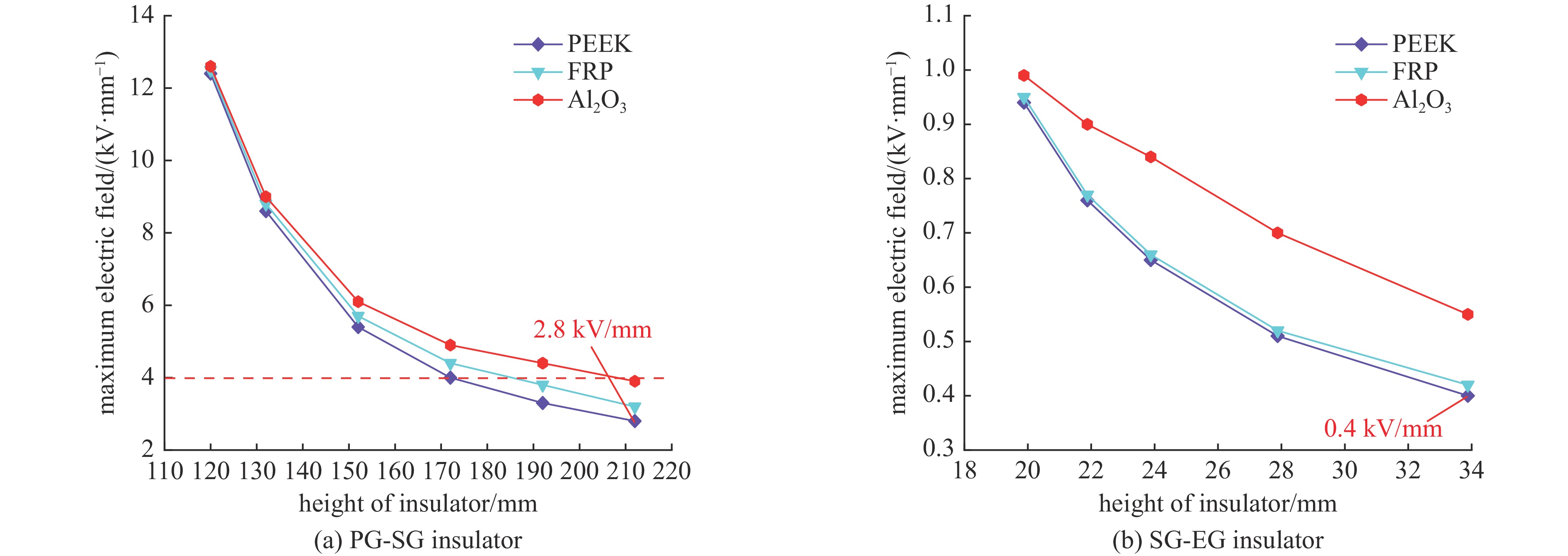
图 4 绝缘体表面最大电场随绝缘体高度变化折线图
Figure 4. Plot of surface maximum electric fields as a function of the height of the insulator
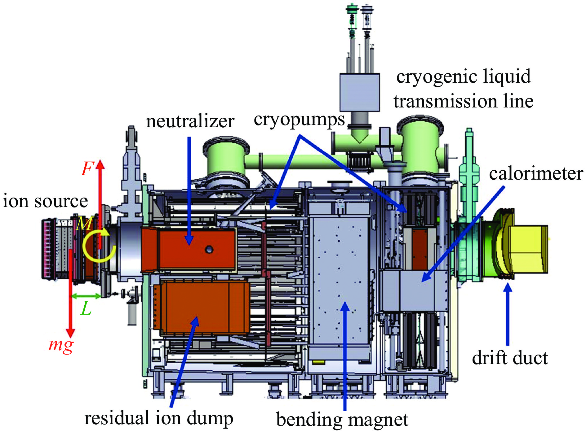
图 7 中性束注入系统中离子源受力图
Figure 7. Force diagram of the ion source in the neutral beam injection system
表 1 1、3、5号位倒角与电场关系表
Table 1. Relationship between chamfers and electric fields at positions 1, 3 and 5
chamfer/mm position 1/(kV·mm−1) position 3/(kV·mm−1) chamfer/mm position 5/(kV·mm−1) 0.4 16.9 14.5 2 16.0 0.6 15.5 13.3 3 14.0 0.7 14.3 12.7 4 12.8 0.8 16.4 12.4 5 12.0  下载: 导出CSV
表 2 材料属性表
Table 2. Material properties
material density/(kg·m−3) tensile strength/MPa shear strength/MPa 304 stainless steel 7930 520 460 PEEK 1320 98 53
下载: 导出CSV
表 3 螺栓轴向力及剪切力汇总表
Table 3. Summary of axial and shear forces on bolts
bolt number axial force/N shear force/N bolt number axial force/N shear force/N 1 −11.214 99.963 19 130.860 97.976 2 −8.466 98.365 20 128.760 95.891 3 −6.444 96.682 21 126.070 94.146 4 −6.560 96.656 22 126.280 94.158 5 −8.453 98.324 23 128.980 95.915 6 −11.173 99.948 24 130.930 97.998 7 −7.288 101.47 25 106.110 100.29 8 −4.003 101.62 26 74.424 100.65 9 −1.080 101.69 27 48.888 100.91 10 0.690 101.69 28 30.771 101.17 11 3.316 101.69 29 18.179 101.39 12 6.334 101.49 30 10.716 101.42 13 10.686 101.40 31 6.257 101.49 14 18.150 101.39 32 3.363 101.69 15 30.780 101.16 33 0.675 101.69 16 48.889 100.92 34 −1.105 101.69 17 74.411 100.65 35 −4.019 101.62 18 105.870 100.25 36 −7.346 101.47
下载: 导出CSV
-
[1] Xie Yahong, Hu Chundong, Liu Sheng, et al. R&D progress of high power ion source on EAST-NBI[J]. Plasma Science and Technology, 2018, 20: 014023. doi: 10.1088/2058-6272/aa8c6c [2] 曹建勇, 魏会领, 刘鹤, 等. HL-2M装置中性束注入加热系统研制进展[J]. 强激光与粒子束, 2018, 30:106001 doi: 10.11884/HPLPB201830.180051Cao Jianyong, Wei Huiling, Liu He, et al. Latest progress of development of the neutral beam injection heating system on HL-2M Tokamak[J]. High Power Laser and Particle Beams, 2018, 30: 106001 doi: 10.11884/HPLPB201830.180051 [3] Ikeda Y, Hanada M, Kamada M, et al. Recent R&D activities of negative-ion-based ion source for JT-60SA[J]. IEEE Transactions on Plasma Science, 2008, 36(4): 1519-1529. doi: 10.1109/TPS.2008.927382 [4] Tanaka Y, Hanada M, Kojima A, et al. Improvement of voltage holding capability in the 500 keV negative ion source for JT-60SA[J]. Review of Scientific Instruments, 2010, 81: 02A719. doi: 10.1063/1.3279399 [5] Wei Jianglong, Xie Yahong, Liu Sheng, et al. Key issues for the filament-arc ion source of EAST neutral beam injector toward high-power and long-pulse operation[J]. Plasma Physics and Controlled Fusion, 2020, 62: 025004. doi: 10.1088/1361-6587/ab5293 [6] Muvvala V N, Joshi J, Shah S, et al. Electro-mechanical design and experimental validation of post insulators for beam source for ITER diagnostic neutral beam[C]//Proceedings of the 26th IAEA Fusion Energy Conference-IAEA CN-234. 2016: 4-12. [7] Gu Yuming, Xie Yahong, Wei Jianglong, et al. The engineering design of quarter size negative beam source for the comprehensive research facility for fusion technology[J]. Fusion Engineering and Design, 2021, 171: 112600. doi: 10.1016/j.fusengdes.2021.112600 [8] Xie Yahong, Hu Chundong, Liu Sheng, et al. Long pulse operation of neutral beam injector on EAST tokamak[J]. Fusion Engineering and Design, 2023, 193: 113744. doi: 10.1016/j.fusengdes.2023.113744 [9] Kuriyama M, Akino N, Ebisawa N, et al. Operation and development on the positive-ion based neutral beam injection system for JT-60 and JT-60U[J]. Fusion Science and Technology, 2002, 42(2/3): 424-434. [10] 张鸿淇, 李志恒, 马少翔, 等. 中性束注入系统加速极电源高压部件设计[J]. 强激光与粒子束, 2024, 36:025011 doi: 10.11884/HPLPB202436.230159Zhang Hongqi, Li Zhiheng, Ma Shaoxiang, et al. Design of high-voltage components for acceleration grid power supply of neutral beam injection system[J]. High Power Laser and Particle Beams, 2024, 36: 025011 doi: 10.11884/HPLPB202436.230159 [11] 杨肖, 毛本将, 何小海. 直流高压加速管轴向绝缘的优化设计[J]. 强激光与粒子束, 2005, 17(10):1595-1600Yang Xiao, Mao Benjiang, He Xiaohai. Optimization design of axial dielectric of DC high-voltage accelerating tube[J]. High Power Laser and Particle Beams, 2005, 17(10): 1595-1600 [12] Agostinetti P, Aprile D, Antoni V, et al. Detailed design optimization of the MITICA negative ion accelerator in view of the ITER NBI[J]. Nuclear Fusion, 2016, 56: 016015. doi: 10.1088/0029-5515/56/1/016015 [13] Xie Yahong, Hu Chundong, Zhao Hongwei. Analysis of ion beam optics of tetrode accelerator for neutral beam injector on the experimental advanced superconducting Tokamak[J]. Nuclear Instruments and Methods in Physics Research Section A: Accelerators, Spectrometers, Detectors and Associated Equipment, 2015, 791: 22-26. [14] Crowley B, Rauch J, Scoville J T. Modeling and experimental studies of the DIII-D neutral beam system[J]. Fusion Engineering and Design, 2015, 96/97: 443-446. doi: 10.1016/j.fusengdes.2015.02.028 [15] Chen Yuqian, Liu Longbin, Xie Yahong, et al. Beam optics analysis for the 120-keV multiaperture accelerator of neutral beam injector[J]. Fusion Science and Technology, 2025, 81(3): 269-278. doi: 10.1080/15361055.2024.2384669 [16] 董刚, 李建功, 潘凤章. 机械设计[M]. 3版. 北京: 机械工业出版社, 1999Dong Gang, Li Jiangong, Pan Fengzhang. Mechanical design[M]. 3rd ed. Beijing: China Machine Press, 1999 [17] 闻邦椿. 机械设计手册 第6版 第2卷[M]. 北京: 机械工业出版社, 2020Wen Bangchun. Mechanical design manual (sixth edition of volume 2)[M]. Beijing: China Machine Press, 2020 -

 点击查看大图
计量
- 文章访问数: 111
- HTML全文浏览量: 42
- PDF下载量: 12
- 被引次数: 0
