

Calibration technology of intense pulse electron beam position monitor
-
摘要: 电子直线感应加速器性能提升对束流探测器提出了高精度测量要求,由此不仅要求高精度的探测器设计装配技术,而且也要求探测器的准确标定。从强流脉冲束流位置探测器测量原理出发,从理论和实验两方面开展强流脉冲束流位置探测器标定技术研究。在理论上采用解析方法,分析了不同的计算处理方法和标定方法的标定效果,提出了特征平面标定,在建立的位置标定系统上,对用于多脉冲电子直线感应加速器的No.23电阻环进行了标定实验研究,实验结果验证了理论分析结果,根据理论和实验研究结果,确定了强流脉冲束流位置探测器标定方法。Abstract: Accurate measurement of the intense pulse electron beam is required by upgrade of linear induction accelerator. This is achieved by not only the technology of beam position monitor (BPM) design and assamble, but also the calibration of BPM. This paper describes the research of calibration technology based on the measuring principle of intense pulse electron beam position monitor in linear induction accelerator. Theoretic method is used to calculate calibrated effects in different signal calculation, polynomial fit and calibration. Characteristic plane calibration is provided according to the analytic results. In the system of BPM position calibration, the No.23 RRM (resistive ring monitor) of multi-pulse electron linear induction accelarator is calibrated by different method. The experimental results validate the theoretic results. The calibration method of intense pulse electron beam position monitor is decided according to the results of research.
-
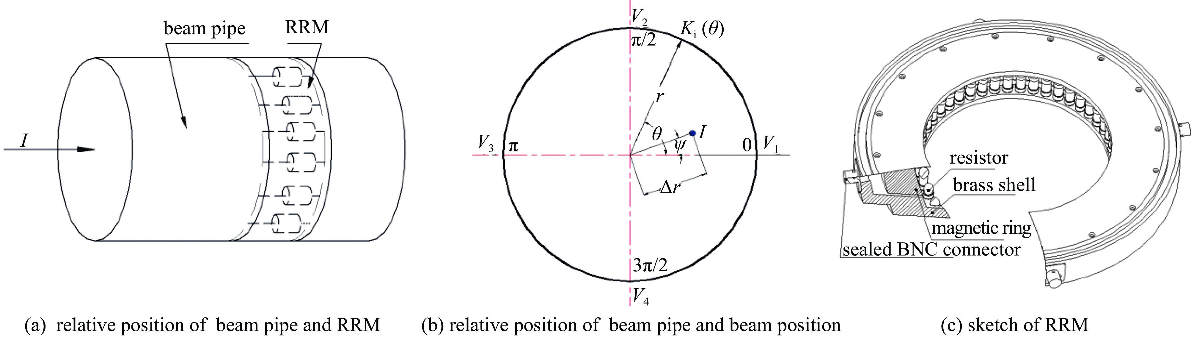
图 1 束管道、电子束和电阻环相对位置及结构示意图
Figure 1. Relative position sketch of beam pipe, beam position and resistive ring monitor (RRM)
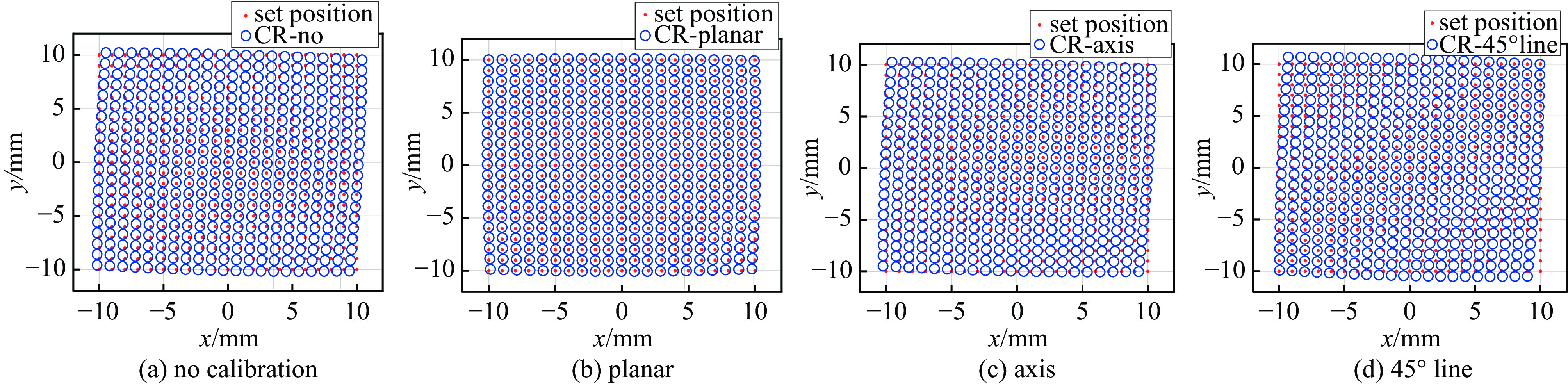
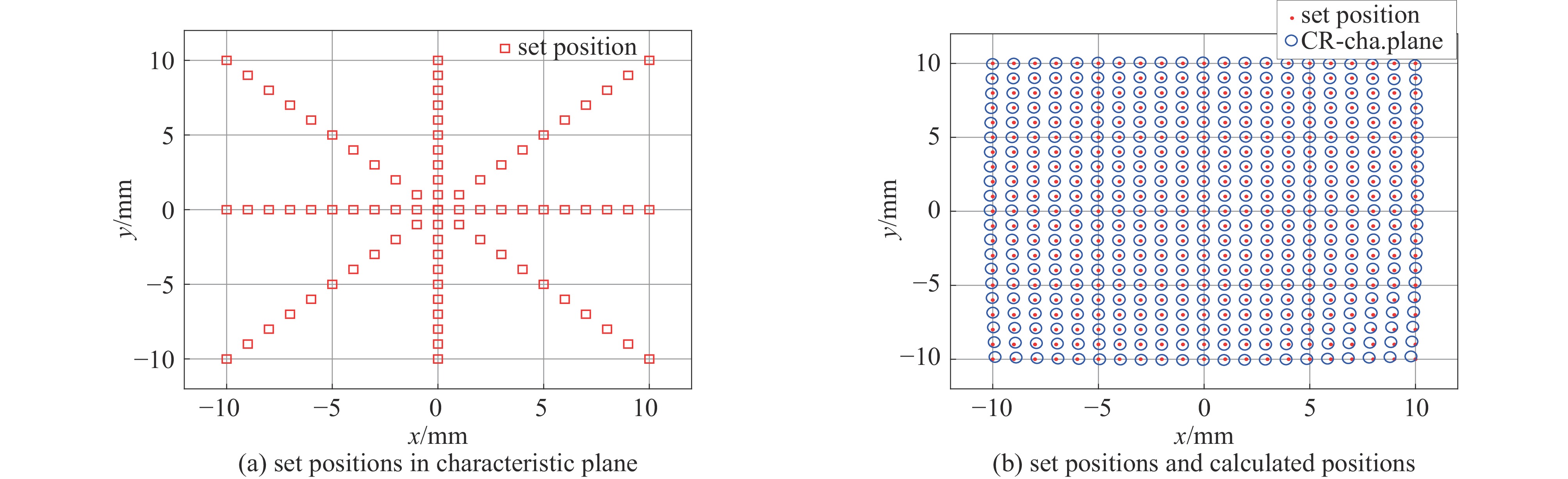
图 3 不同标定方法的标准位置和 测量位置在一阶拟合条件下的比较
Figure 3. Comparatison between set positions and calculated positions of different calibration in condition of n=1
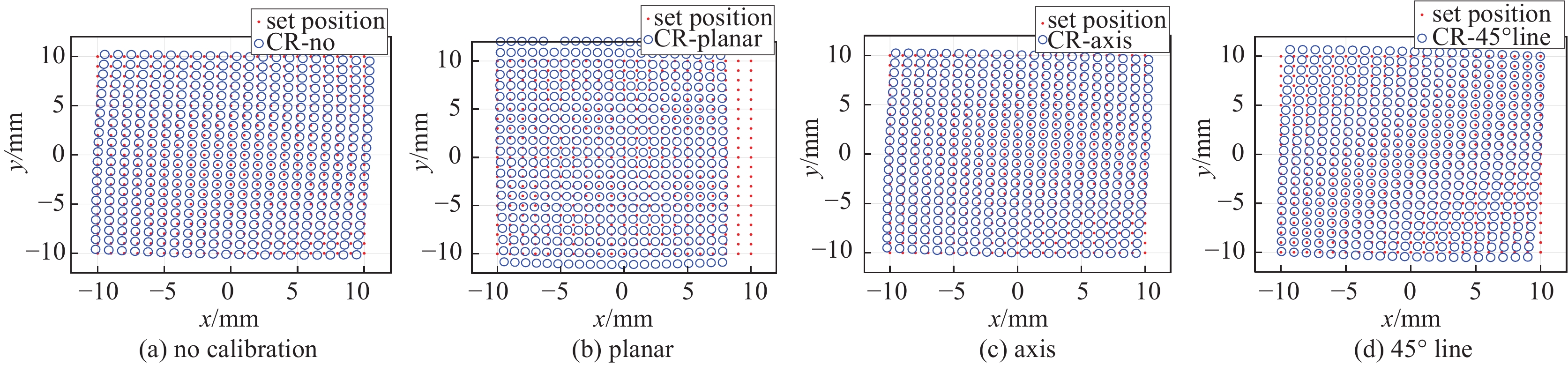
图 4 不同标定方法的标准位置和测量位置在四阶拟合条件下的比较
Figure 4. Comparison between set positions and calculated positions of different calibration in condition of n=4
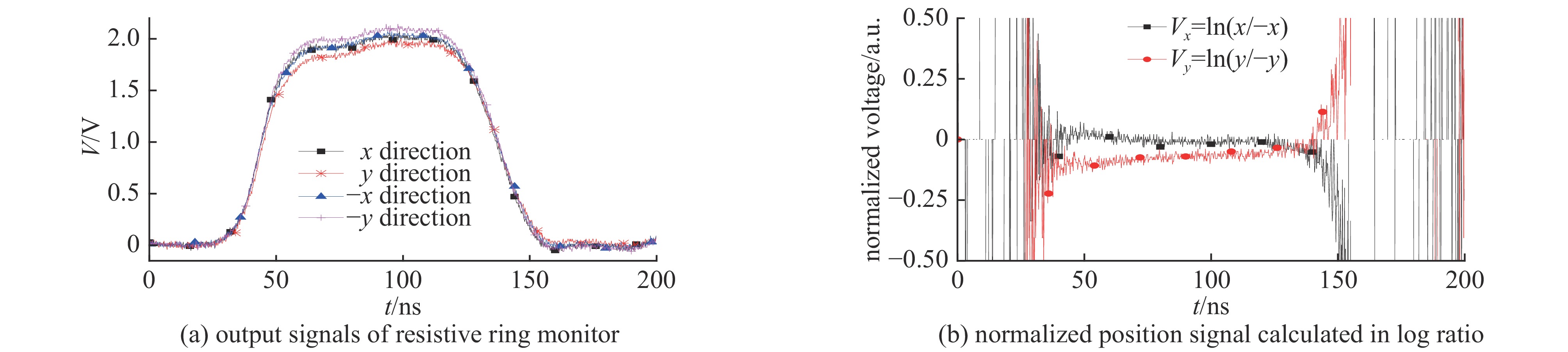
图 6 电阻环在位置标定系统中的测量信号及处理结果
Figure 6. Measurment of resistive ring monitor in calibration system and signal processing result
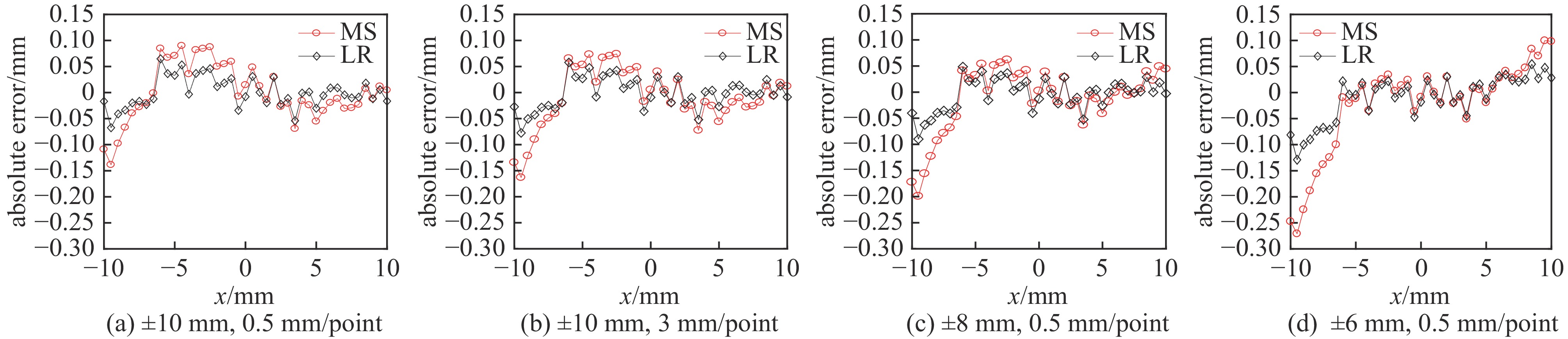
图 7 不同标定位置步进和范围处理结果在x方向的位置误差分布
Figure 7. Position error distribution in x direction in different calibration position span and range
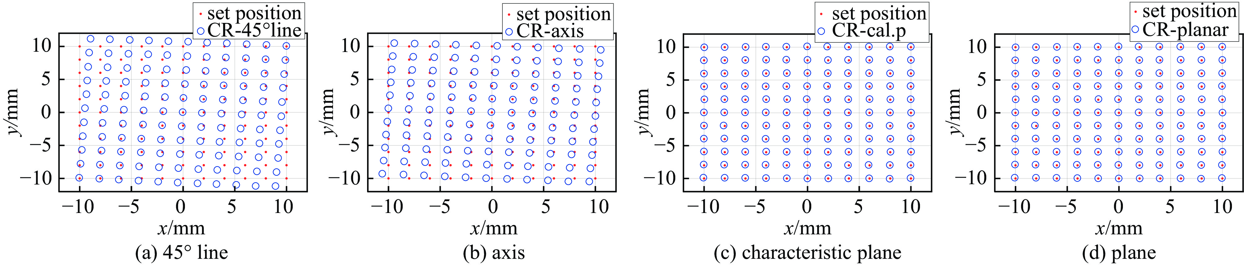
图 8 不同标定方法的位置测量结果与标准位置比较
Figure 8. Set position and measured position of different calibration method
表 1 不同方法的标定效果
Table 1. Calculated results of different normalization, calibration and polynomial fit
monitor parameter normalization calibration average of absolute value of position error/mm n=1 n=2 n=3 n=4 s1=1 minus/sum no calibration 2.77 2.77 2.77 2.77 s2=1 planar 0.17 0.75 23.04 23.93 s3=1.05 axis 0.23 0.23 1.75 1.67 s4=0.9 45° line 0.22 0.24 3.63 3.74 Δx0=0 log ratio no calibration 2.85 2.85 2.85 2.85 Δy0=0 planar 0.06 0.06 7.56 7.56 θx=0 axis 0.08 0.08 0.61 0.61 θy=0 45° line 0.07 0.07 1.20 1.20 s1=1 minus/sum no calibration 3.00 3.00 3.00 3.00 s2=1 planar 0.19 2.44 26.92 28.27 s3=1 axis 0.25 0.50 2.15 1.75 s4=1 45° line 0.27 0.37 3.67 2.92 Δx0=1 mm log ratio no calibration 3.00 3.00 3.00 3.00 Δy0=−2 mm planar 0.06 0.82 8.90 9.45 θx=0 axis 0.09 0.17 0.76 0.75 θy=0 45° line 0.09 0.11 1.17 1.18 s1=1 minus/sum no calibration 0.57 0.57 0.57 0.57 s2=1 planar 0.18 1.66 5.30 5.40 s3=1.05 axis 0.39 0.40 1.04 1.03 s4=0.9 45° line 0.55 0.56 2.04 1.97 Δx0=1 mm log ratio no calibration 0.39 0.39 0.39 0.39 Δy0=−2 mm planar 0.06 0.84 1.82 1.94 θx=0.03 rad axis 0.37 0.37 0.49 0.49 θy=0.04 rad 45° line 0.50 0.50 0.55 0.55  下载: 导出CSV
表 2 对数比和一阶拟合条件下不同标定方法在不同探测器参数下的标定效果
Table 2. Calculated results of different monitor parameter and calibration in conditions of log ratio and n=1
monitor parameter average of absolute value of position error/mm no calibration planar axis 45° line s1=1.05, s2=0.9, s3=0.8, s4=1.1; Δx0=0, Δy0=0; θx =0, θy =0 8.74 0.06 0.08 0.07 s1=s2=1, s3=1, s4=1;Δx0=-3 mm, Δy0=4 mm, θx =0,θy =0 4.00 0.05 0.06 0.06 s1=s2=1, s3=1, s4=1; Δx0=0, Δy0=0,θx =-0.04 rad, θy =0.05 rad 0.21 0.03 0.21 0.24 s1=1.05, s2=0.9, s3=0.8, s4=1.1;Δx0=-3 mm, Δy0=4 mm, θx =-0.04 rad, θy =0.05 rad 2.37 0.10 0.51 0.60 s1=s2=1, s3=1.05, s4=0.9;Δx0=1 mm, Δy0=-2 mm, θx =0.03 rad, θy =0.04 rad 0.39 0.06 0.37 0.50
下载: 导出CSV
表 3 特征平面标定与其它标定方法的结果比较
Table 3. Comparison between characteristic plane calibration and others
monitor parameters average of absolute value of position error/mm s1=s2=1, s3=1.05, s4=0.9; Δx0=1 mm,
Δy0=−2 mm; θx=0.03 rad, θy =0.04 radno calibration planar axis 45° line characteristic plane 1 mm/point 2 mm/point 3 mm/point 0.3905 0.0634 0.3701 0.4985 0.0649 0.0653 0.0659
下载: 导出CSV
表 4 直线标定实验在不同位置步进和范围的处理结果
Table 4. Processing results of line calibration experiment in different position span and range
span and range normalization klx(1) klx (0) kly(1) kly(0) xerror/mm yerror/mm 0.5 mm/point
−10 mm~10 mmminus/sum 83.38 0.15 94.62 1.63 0.0437 0.0479 log ratio 20.66 0.17 23.35 1.62 0.0230 0.0284 1 mm/point
−10 mm~10 mmminus/sum 83.39 0.15 94.65 1.63 0.0437 0.0483 log ratio 20.65 0.17 23.34 1.62 0.0232 0.0285 3 mm/point
−10 mm~10 mmminus/sum 83.24 0.16 94.64 1.63 0.0442 0.0487 log ratio 20.64 0.17 23.34 1.62 0.0234 0.0284 0.5 mm/point
−8 mm~8 mmminus/sum 82.95 0.16 94.02 1.63 0.0451 0.0499 log ratio 20.62 0.18 23.29 1.62 0.0244 0.0304 0.5 mm/point
−6 mm~6 mmminus/sum 82.41 0.17 93.63 1.63 0.0594 0.0587 log ratio 20.55 0.18 23.27 1.63 0.0336 0.0333
下载: 导出CSV
表 5 特征平面标定实验在不同位置步进和范围的处理结果
Table 5. Processing results of characteristic plane calibration experiment in different position span and range
span range kpx(0) kpx(1) kpx(2) kpy(0) kpy(1) kpy(2) xerror/mm yerror/mm 1 mm/point ±10 mm 0.08 21.47 −1.22 −0.24 1.21 22.12 0.0249 0.0218 2 mm/point ±10 mm 0.08 21.47 −1.22 −0.24 1.21 22.12 0.0251 0.0224 3 mm/point ±10 mm 0.08 21.47 −1.22 −0.24 1.21 22.12 0.0254 0.0218 1 mm/point ±10 mm 0.08 21.47 −1.22 −0.24 1.21 22.12 0.0253 0.0218 1 mm/point ±8 mm 0.08 21.47 −1.22 −0.24 1.21 22.12 0.0255 0.0228 1 mm/point ±6 mm 0.08 21.47 −1.22 −0.24 1.21 22.12 0.0249 0.0218
下载: 导出CSV
表 6 平面标定实验在不同位置范围的处理结果
Table 6. Processing results of plane calibration experiment in different position range
position range/mm kpx(0) kpx(1) kpx(2) kpy(0) kpy(1) kpy(2) xerror/mm yerror/mm ±10 0.24 21.51 −1.19 −0.27 1.21 21.91 0.0235 0.0222 ±8 0.25 21.50 −1.19 −0.27 1.22 21.92 0.0237 0.0223 ±6 0.25 21.55 −1.16 −0.27 1.20 21.91 0.0266 0.0225 ±4 0.26 21.66 −1.15 −0.27 1.20 21.81 0.0438 0.0302
下载: 导出CSV
表 7 平面标定实验在不同标定方法的处理结果
Table 7. Processing results of plane calibration experiment using different calibration method
calibration kx(0) kx(1) kx(2) ky(0) ky(1) ky(2) xerror/mm yerror/mm 45° line 0.23 20.44 / −0.32 / 23.33 0.3778 0.4463 −45° line 0.24 22.84 / −0.25 / 20.87 0.4239 0.3751 axis 0.24 21.56 / −0.29 / 21.91 0.2976 0.3086 characterictic plane 0.25 21.50 −1.21 −0.27 1.21 21.92 0.0243 0.0224 plane 0.24 21.51 −1.19 −0.27 1.21 21.91 0.0235 0.0222
下载: 导出CSV
-
[1] 何文龙. 电阻环法模拟测量电子束流动大小和位置[C]//中国工程物理研究院流体物理研究所 · 加速器物理及应用研究室. 10MeV直线感应加速器会议文集. 1994He Wenlong. Intensity and position measurements of an intense particle beam using resistance ring[C]//Institute of Fluid Physics, Chinese Academy of Engineering Physics · Accelerator Physics and Application Laboratory. Proceedings of The Conference on 10MeV Liner Induction Accelerator. 1994 [2] Fessenden T J, Stallard B W, Berg G G. Beam current and position monitor for the Astron accelerator[J]. Review of Scientific Instruments, 1972, 43(12): 1789-1792. doi: 10.1063/1.1685566 [3] 谢宇彤, 代志勇, 韩青. 电阻环束流探测器的标定[J]. 强激光与粒子束, 2002, 14(1):151-155Xie Yutong, Dai Zhiyong, Han Qing. Improvement on the accuracy of beam bugs in linear induction accelerator[J]. High Power Laser and Particle Beams, 2002, 14(1): 151-155 [4] 李勤, 李洪, 陈楠, 等. 用于测量强流脉冲电子束的B-dot[J]. 强激光与粒子束, 2009, 21(9):1390-1394Li Qin, Li Hong, Chen Nan, et al. B-dot monitor for intense electron beam measurement[J]. High Power Laser and Particle Beams, 2009, 21(9): 1390-1394 [5] 赵籍九, 尹兆升. 粒子加速器技术[M]. 北京: 高等教育出版社, 2006Zhao Jijiu, Yin Zhaosheng. Particle accelerator technology[M]. Beijing: Higher Education Press, 2006 [6] 王盛昌, 王安鑫, 徐韬光. 用于质子加速器的壁电流探头的研制[J]. 强激光与粒子束, 2012, 24(9):2179-2182 doi: 10.3788/HPLPB20122409.2179Wang Shengchang, Wang Anxin, Xu Taoguang. Design of wall current monitor for proton accelerators[J]. High Power Laser and Particle Beams, 2012, 24(9): 2179-2182 doi: 10.3788/HPLPB20122409.2179 [7] 邹俊颖. HLS II注入器束流位置测量系统的研制及应用研究[D]. 合肥: 中国科学技术大学, 2014Zou Junying. Development and application of injector beam position monitor system at HLS Ⅱ[D]. Hefei: University of Science and Technology of China, 2014 [8] 王建新, 刘宇, 张浩, 等. 积分式束流变压器的标定研究[J]. 原子能科学技术, 2015, 49(s2):620-623Wang Jianxin, Liu Yu, Zhang Hao, et al. Calibration of integrating current transformer[J]. Atomic Energy Science and Technology, 2015, 49(s2): 620-623 [9] 李吉浩, 孙葆根, 何多慧, 等. HLS直线加速器条带束流位置检测器基于对数比方法的标定[J]. 原子能科学技术, 2007, 41(3):339-342 doi: 10.7538/yzk.2007.41.03.0339Li Jihao, Sun Baogen, He Duohui, et al. Mapping of strip line beam position monitor at HLS LINAC based on logarithm ratio processing method[J]. Atomic Energy Science and Technology, 2007, 41(3): 339-342 doi: 10.7538/yzk.2007.41.03.0339 [10] 王贵诚, 王筠华, 蒋道满, 等. BPM定标系统及其应用[J]. 核技术, 2003, 26(4):254-256Wang Guicheng, Wang Junhua, Jiang Daoman, et al. A BPM calibration system and its application[J]. Nuclear Techniques, 2003, 26(4): 254-256 [11] Johnson J B, Bishofberger K A. Initial testing of the scorpius beam position monitors[R]. LA-UR-21-28704. [12] Broste W B. Beam position monitor: sensors, calibration and analysis[R]. LA-UR-22-27440, 2021. [13] 李勤, 何小中, 蒋薇, 等. 强流脉冲束流位置探测器标定装置物理设计[J]. 强激光与粒子束, 2023, 35:034002 doi: 10.11884/HPLPB202335.220224Li Qin, He Xiaozhong, Jiang Wei, et al. Physical design of calibrated device for intense pulse electron beam position monitor[J]. High Power Laser and Particle Beams, 2023, 35: 034002 doi: 10.11884/HPLPB202335.220224 [14] Carlson R L, Ridlon R N, Stout L E. Multigigahertz beam current and position monitor for relativistic electron beams[J]. Review of Scientific Instruments, 1986, 57(10): 2471-2474. doi: 10.1063/1.1139095 [15] Rienstra W W, Haworth M D. An exact analysis for beam centroid position monitors used in pulsed intense relativistic electron-beam experiments[J]. Review of Scientific Instruments, 1991, 62(10): 2363-2367. doi: 10.1063/1.1142246 [16] 数学手册[M]. 北京: 高等教育出版社, 1997Mathematical manual[M]. Beijing: Higher Education Press, 1997 -


 点击查看大图
计量
- 文章访问数: 34
- HTML全文浏览量: 19
- PDF下载量: 5
- 被引次数: 0
