

Theoretical investigation into effect of laser focal spot size on extreme ultraviolet radiation
-
摘要: 为了解激光焦斑尺寸对极紫外转换效率影响及产生影响的物理机制,通过理论解析的方式提出了激光烧蚀平面靶产生冕区等离子体的二维瞬态膨胀模型来研究激光焦斑对极紫外光转换效率的影响。发现在激光光强7.45×10¹⁰ W/cm2、半高全宽5 ns、波长
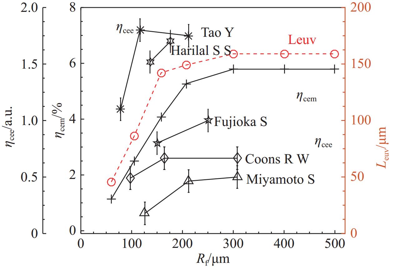
1064 nm时,随着激光焦斑半径从60 μm增大到300 μm,相应地极紫外转换效率从1%增大到5.5%;而焦斑半径大于300 μm后,相应地极紫外转换效率保持在5.5%。这是由于激光烧蚀平面靶产生的冕区等离子体从初始的一维膨胀到随后的二维膨胀过程决定了发射极紫外光的等离子体区的饱和尺寸,并最终决定了极紫外光的转换效率。转换效率随焦斑半径变化的趋势可以解释激光烧蚀锡靶实验观察到的物理现象。Abstract: To understand the effect of laser focal spot size on the extreme ultraviolet conversion efficiency and the physical mechanism that produces the effect, we developed a two-dimensional transient expansion model of laser ablation of planar target to produce coronal plasma by means of theoretical analysis. It is found that under condition with light intensity of 7.45×10¹⁰ W/cm2, full width at half maxima of 5 ns, wavelength of1064 nm, as the laser focal spot radius increases from 60 μm to 300 μm, the corresponding extreme ultraviolet conversion efficiency increases from 1% to 5.5%, while the corresponding extreme ultraviolet conversion efficiency stays at 5.5% after the focal spot radius is larger than 300 μm. This is due to the fact that the plasma in the coronal region generated by laser ablation of planar targets expands from the initial one-dimensional expansion to the subsequent two-dimensional expansion, which determines the saturation size of the plasma region emitting extreme ultraviolet light and ultimately determines the conversion efficiency of the extreme ultraviolet light. Our theoretical analysis on trend of conversion efficiency with focal spot radius can explain the physical phenomena observed in the laser ablation of a tin target experiment. -
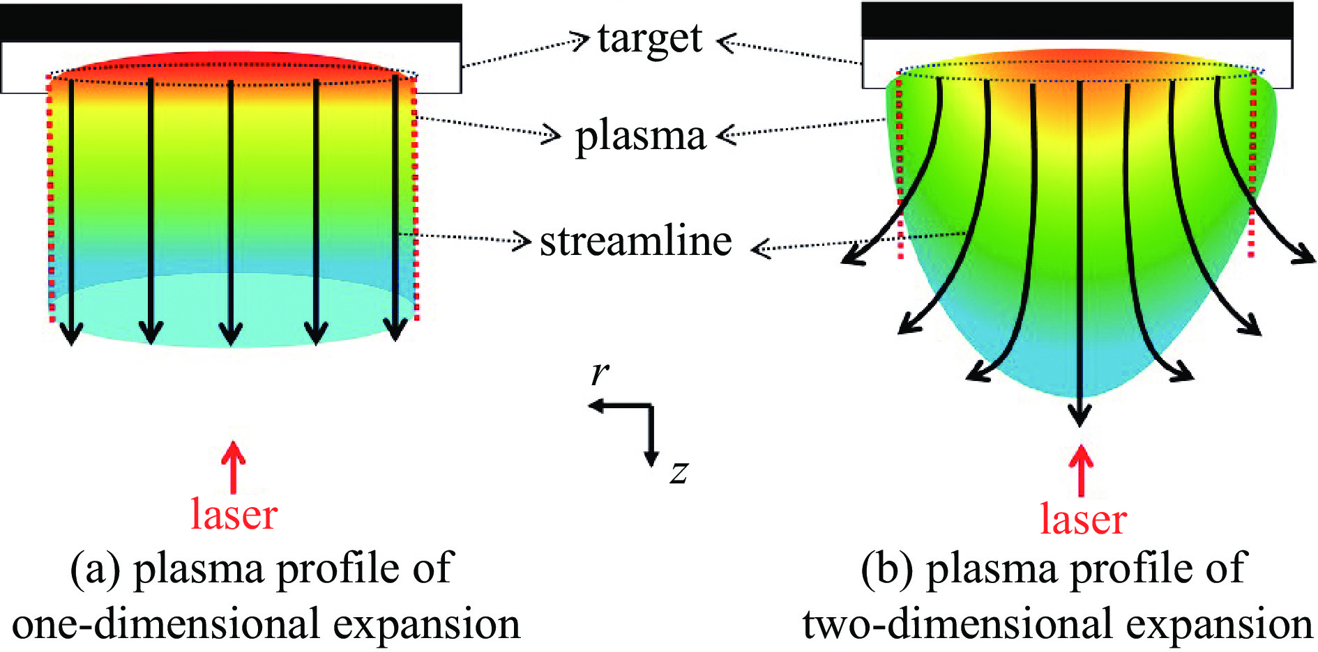
图 1 激光烧蚀平面靶产生的等离子体的膨胀过程的示意图
Figure 1. Schematic diagram of the plasma expansion of laser-ablated planar target
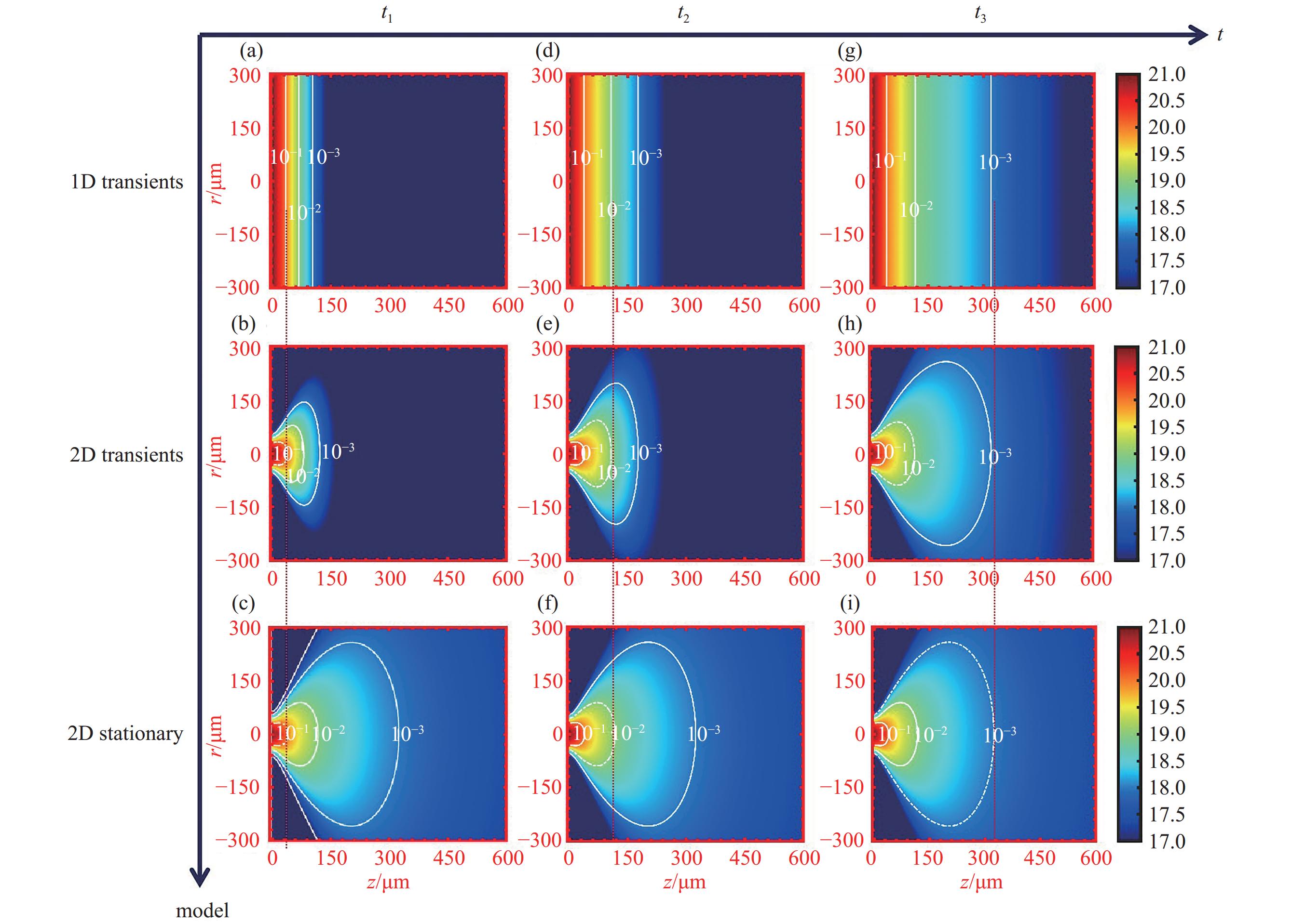
图 3 二维瞬态膨胀的密度分布建模过程
Figure 3. The process of modelling the density distribution of a two-dimensional transient expansion
Figures (a)(b)(c) are the density distributions of the characteristic moment t1 when the isodensity surface 0.1 nc reaches the steady-state position, figures (d)(e)(f) are the density distributions of the characteristic moment t2 when the isodensity surface 0.01nc reaches the steady-state position, and figures (g)(h)(i) are the density distributions of the characteristic moment t3 when the isodensity surface 0.001nc reaches the steady-state position; figures (a)(d)(g) are the density distributions of one-dimensional expansion, figures (d)(e)(f) are the density distributions of two-dimensional transient expansion, figures (c)(f)(i) are the density distributions of two-dimensional stationary expansion. The density profiles of the one-dimensional expansion corresponding to (a)(d)(g) and the two-dimensional steady state expansion corresponding to (c)(f)(i) are multiplied to obtain the density distribution of the two-dimensional transient expansion corresponding to (d)(e)(f).
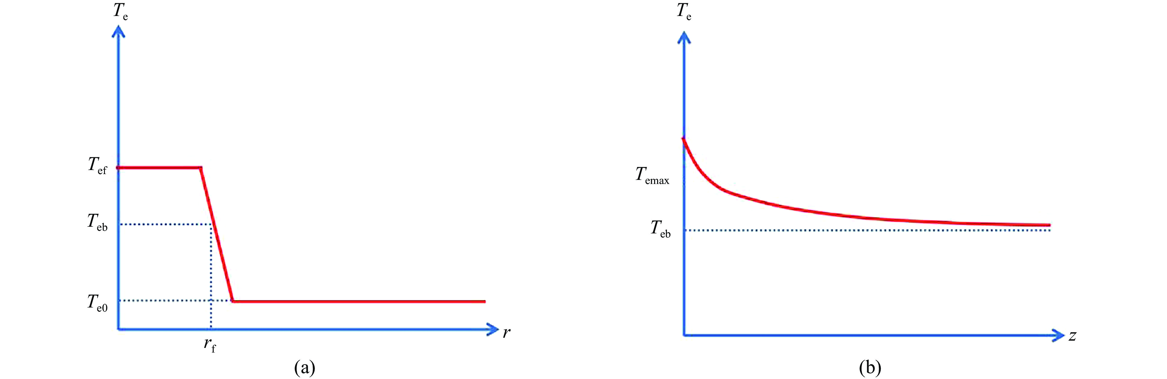
图 4 横向(a)与纵向(b)上的电子温度分布
Figure 4. Electron temperature distribution in the transverse (a) and longitudinal (b) directions
图 5 不同焦斑半径时二维稳态膨胀的电子密度ne(cm−3)空间分布
Figure 5. Spatial distribution of electron density at 2D steady-state expansion vs laser focal spot radii. The cases with laser focal spot radius of 60 μm, 105 μm, and 158 μm are present from left to right
图 6 不同焦斑尺寸下各特征密度面的稳态位置及到达相应位置的时间
Figure 6. Steady state position and time to reach the corresponding position for each characteristic density surface for different focal spot sizes
图 7 焦斑半径60 μm,电子密度(a)、电子温度(b)、发射率(c)和净发射率(d)的空间分布
Figure 7. Spatial distribution of electron density(a), electron temperature(b), emissivity(c), net emissivity(d) at laser focal spot radius of 60 μm, and t = 1 ns, 2 ns, 7 ns. The 0.1nc density surface reaches stable location at 1 ns
图 8 焦斑半径105 μm,电子密度(a)、电子温度(b)、发射率(c)和净发射率(d)的空间分布
Figure 8. Spatial distribution of electron density(a), electron temperature(b), emissivity(c), net emissivity(d) at laser focal spot radius of 105 μm, and t = 2 ns, 4 ns, 11 ns from left to right. The 0.1nc density surface reaches stable location at 2 ns
图 9 焦斑半径158 μm,电子密度(a)、电子温度(b)、发射率(c)和净发射率(d)的空间分布
Figure 9. Spatial distribution of electron density(a), electron temperature(b), emissivity(c), net emissivity(d) at laser focal spot radius of 158 μm, and t = 3 ns, 6 ns, 15 ns from left to right. The 0.1nc density surface reaches stable location at 3 ns
图 10 焦斑半径60 μm,t=1 ns、2 ns、7 ns时,在R=0处沿着纵向的一维物理量分布
Figure 10. One-dimension longitudinal profiles along the R=0 line at laser focal spot radius of 60 μm at the moments of t=1 ns, 2 ns, 7 ns
图 11 焦斑半径105 μm,t=2 ns、4 ns、11 ns时,在R=0处沿着纵向的一维物理量分布
Figure 11. One-dimension longitudinal profiles along the R=0 line at laser focal spot radius of 105 μm at the moments of t=2 ns, 4 ns, 11 ns
图 12 焦斑半径158 μm,t=3 ns、6 ns、15 ns时,在R=0处沿着纵向的一维物理量分布
Figure 12. One-dimension longitudinal profiles along the R=0 line at laser focal spot radius of 158 μm, at the moments of t=3 ns, 6 ns, 15 ns
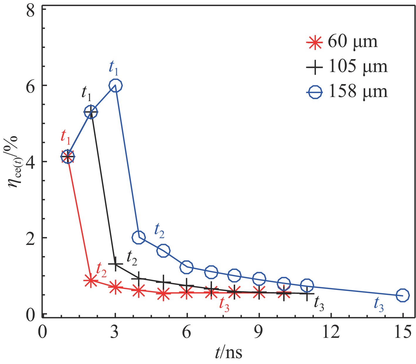
图 13 不同焦斑尺寸下瞬时转换效率ηce(t)随时间的变化
Figure 13. Temporal evolution of instantaneous conversion efficiency ηce(t) at laser focal spot sizes of 60 μm (red), 105 μm (black), and 158 μm (blue)
-
[1] Wagner C, Harned N. EUV lithography: lithography gets extreme[J]. Nature Photonics, 2010, 4(1): 24-26. doi: 10.1038/nphoton.2009.251 [2] Bakshi V. EUV sources for lithography[M]. Bellingham: SPIE, 2006. [3] Banine V Y, Koshelev K N, Swinkels G H P M. Physical processes in EUV sources for microlithography[J]. Journal of Physics D: Applied Physics, 2011, 44: 253001. doi: 10.1088/0022-3727/44/25/253001 [4] Versolato O O. Physics of laser-driven tin plasma sources of EUV radiation for nanolithography[J]. Plasma Sources Science and Technology, 2019, 28: 083001. doi: 10.1088/1361-6595/ab3302 [5] Endo A, Hoshino H, Suganuma T, et al. Laser produced EUV light source development for HVM[C]//Proceedings of SPIE 6517, Emerging Lithographic Technologies XI. San Jose: SPIE, 2007: 65170O. [6] Freeman J R, Harilal S S, Hassanein A. Enhancements of extreme ultraviolet emission using prepulsed Sn laser-produced plasmas for advanced lithography applications[J]. Journal of Applied Physics, 2011, 110: 083303. doi: 10.1063/1.3647779 [7] Nishihara K, Sunahara A, Sasaki A, et al. Advanced laser-produced EUV light source for HVM with conversion efficiency of 5-7% and B-field mitigation of ions[C]//Proceedings of SPIE 6921, Emerging Lithographic Technologies XII. San Jose: SPIE, 2008: 69210Y. [8] Tanaka H, Matsumoto A, Akinaga K, et al. Comparative study on emission characteristics of extreme ultraviolet radiation from CO2 and Nd: YAG laser-produced tin plasmas[J]. Applied Physics Letters, 2005, 87: 041503. doi: 10.1063/1.1989441 [9] Aota T, Tomie T. Ultimate efficiency of extreme ultraviolet radiation from a laser-produced plasma[J]. Physical Review Letters, 2005, 94: 015004. doi: 10.1103/PhysRevLett.94.015004 [10] Okuno T, Fujioka S, Nishimura H, et al. Low-density tin targets for efficient extreme ultraviolet light emission from laser-produced plasmas[J]. Applied Physics Letters, 2006, 88: 161501. doi: 10.1063/1.2195693 [11] 林楠, 杨文河, 陈韫懿, 等. 极紫外光刻光源的研究进展及发展趋势[J]. 激光与光电子学进展, 2022, 59:0922002Lin Nan, Yang Wenhe, Chen Yunyi, et al. Research progress and development trend of extreme ultraviolet lithography source[J]. Laser & Optoelectronics Progress, 2022, 59: 0922002 [12] Miyamoto S, Shimoura A, Amano S, et al. Laser wavelength and spot diameter dependence of extreme ultraviolet conversion efficiency in ω, 2ω, and 3ω Nd: YAG laser-produced plasmas[J]. Applied Physics Letters, 2005, 86: 261502. doi: 10.1063/1.1968415 [13] Tao Y, Harilal S S, Tillack M S, et al. Effect of focal spot size on in-band 13.5 nm extreme ultraviolet emission from laser-produced Sn plasma[J]. Optics Letters, 2006, 31(16): 2492-2494. doi: 10.1364/OL.31.002492 [14] Fujioka S, Nishimura H, Nishihara K, et al. Opacity effect on extreme ultraviolet radiation from laser-produced tin plasmas[J]. Physical Review Letters, 2005, 95: 235004. doi: 10.1103/PhysRevLett.95.235004 [15] Harilal S S, Coons R W, Hough P, et al. Influence of spot size on extreme ultraviolet efficiency of laser-produced Sn plasmas[J]. Applied Physics Letters, 2009, 95: 221501. doi: 10.1063/1.3270526 [16] Coons R W, Campos D, Crank M, et al. Comparison of EUV spectral and ion emission features from laser-produced Sn and Li plasmas[C]//Proceedings of SPIE 7636, Extreme Ultraviolet (EUV) Lithography. San Jose: SPIE, 2010: 763636. [17] Atzeni S, Meyer-ter-Vehn J. 惯性聚变物理[M]. 沈百飞, 译. 北京: 科学出版社, 2008Atzeni S, Meyer-ter-Vehn J. Physics of inertial fusion[M]. Shen Baifei, trans. Beijing: Science Press, 2008 [18] Hu G Y, Zhang J Y, Zheng J, et al. Angular distribution and conversion of multi-keV L-shell X-ray sources produced from nanosecond laser irradiated thick-foil targets[J]. Laser and Particle Beams, 2008, 26(4): 661-670. doi: 10.1017/S0263034608000682 [19] Hu Guangyue, Zheng Jian, Shen Baifei, et al. Characterization of a multi-keV X-ray source produced by nanosecond laser irradiation of a solid target: the influence of laser focus spot and target thickness[J]. Physics of Plasmas, 2008, 15: 023103. doi: 10.1063/1.2831034 [20] Hu Guangyue, Liu Shenye, Zheng Jian, et al. Efficient K-shell X-ray sources produced with titanium foils[J]. Physics of Plasmas, 2007, 14: 033103. doi: 10.1063/1.2446286 [21] 胡广月, 刘慎业, 张继彦, 等. 长脉冲keV X射线源的辐射特征[J]. 强激光与粒子束, 2007, 19(5):771-776Hu Guangyue, Liu Shenye, Zhang Jiyan, et al. Emission characteristic of long laser pulse keV X-ray source[J]. High Power Laser and Particle Beams, 2007, 19(5): 771-776 [22] Fabbro R, Max C, Fabre E. Planar laser-driven ablation: effect of inhibited electron thermal conduction[J]. Physics of Fluids, 1985, 28(5): 1463-1481. doi: 10.1063/1.864982 [23] Merino M, Cichocki F, Ahedo E. A collisionless plasma thruster plume expansion model[J]. Plasma Sources Science and Technology, 2015, 24: 035006. doi: 10.1088/0963-0252/24/3/035006 [24] Spitzer L Jr, Härm R. Transport phenomena in a completely ionized gas[J]. Physical Review, 1953, 89(5): 977-981. doi: 10.1103/PhysRev.89.977 [25] Sasaki A, Sunahara A, Furukawa H, et al. Modeling of radiative properties of Sn plasmas for extreme-ultraviolet source[J]. Journal of Applied Physics, 2010, 107: 113303. doi: 10.1063/1.3373427 [26] Nishihara K, Sunahara A, Sasaki A, et al. Plasma physics and radiation hydrodynamics in developing an extreme ultraviolet light source for lithography[J]. Physics of Plasmas, 2008, 15: 056708. doi: 10.1063/1.2907154 -

 下载:
下载:
 点击查看大图
计量
- 文章访问数: 247
- HTML全文浏览量: 103
- PDF下载量: 28
- 被引次数: 0
