

Design of RF shielding CF flange copper ring structure
-
摘要: 高能电子加速器中,束流与真空室相互作用产生的尾场会引发束流不稳定性,此现象在高重频(>105 Hz)超导加速器中尤为明显。全金属加速器真空室大量使用的CF刀口法兰,其连接处截面突变是导致产生束流耦合阻抗的主要来源之一。设计了一种RF屏蔽型法兰-密封圈连接结构,其目的是通过实现法兰-密封圈-法兰预紧密封后的平滑过渡,有效减少阻抗。首先采用3D电磁仿真CST软件对比仿真了连接过渡段不同径向台阶和轴向间隙参数下的阻抗效应,给出了相关参数的允许范围。然后通过ANSYS软件对屏蔽法兰-铜圈结构进行了形变仿真,初步制定了不同型号的屏蔽密封圈的内径几何参数,在屏蔽法兰-密封圈的真空密封试验中,验证了预紧力矩≥6 N·m时即可实现有效的超高真空密封,并且通过屏蔽法兰-密封铜圈过渡段径向台阶和轴向间隙测试试验,得到了最优预紧力矩和屏蔽铜圈的关键尺寸参数。最后采用对光滑真空管段、标准法兰-密封圈过渡段和屏蔽法兰-密封圈过渡段的功率损失和阻抗进行了仿真计算,验证了所设计的RF屏蔽型法兰-密封圈连接结构可以有效地实现阻抗屏蔽。Abstract:
Background High-repetition-rate electron accelerators face beam instabilities induced by wake fields from beam-vacuum chamber interactions. Geometric discontinuities at ubiquitous Con Flat (CF) knife-edge flange connections are a dominant source of beam-induced impedance in all-metal vacuum chambers.Purpose To mitigate this impedance, this paper designs an RF-shielded flange-gasket connection structure achieving a smooth post-tightening transition at the interface, thereby minimizing impedance.Methods 1. Electromagnetic Simulation: 3D simulations (CST) analyzed impedance effects of radial step heights and axial gaps at the transition, establishing allowable parameter ranges. 2. Deformation Simulation: ANSYS simulations modeled the shielded flange-copper gasket assembly to preliminarily determine inner diameter specifications for various gasket models. 3. Vacuum Sealing Tests: Verified ultra-high vacuum integrity under applied tightening torque. 4. Transition Geometry Testing: Measured the achieved radial step and axial gap post-tightening to define optimal copper gasket dimensions and tightening torque. 5. Comparative Simulation: CST simulations compared power loss and impedance for smooth chambers, standard flange-gasket transitions, and the proposed shielded transition.Results 1. Electromagnetic simulations defined critical tolerance ranges for radial step and axial gap. 2. Deformation simulations provided initial gasket inner diameter specifications. 3. Vacuum tests confirmed effective sealing at a tightening torque≥6 N·m. 4. Transition testing established the optimal tightening torque and key copper gasket dimensions ensuring minimal geometric discontinuity. 5. Comparative simulations demonstrated that the RF-shielded flange-gasket transition significantly reduces power loss and impedance compared to a standard CF transition, achieving performance close to that of a smooth vacuum chamber.Conclusions The designed RF-shielded flange-gasket connection structure effectively minimizes geometric discontinuity at the joint. Through combined electromagnetic, mechanical, and vacuum testing, critical parameters (radial step, axial gap, gasket dimensions, tightening torque≥6 N · m) were optimized. Electromagnetic verification confirms this design provides effective impedance shielding, offering a solution to mitigate wake-field-induced instabilities at flange connections in high-energy accelerators.-
Key words:
- Electron accelerator /
- High repetition rate /
- Wakefield /
- beam coupling impedance /
- RF shielding
-
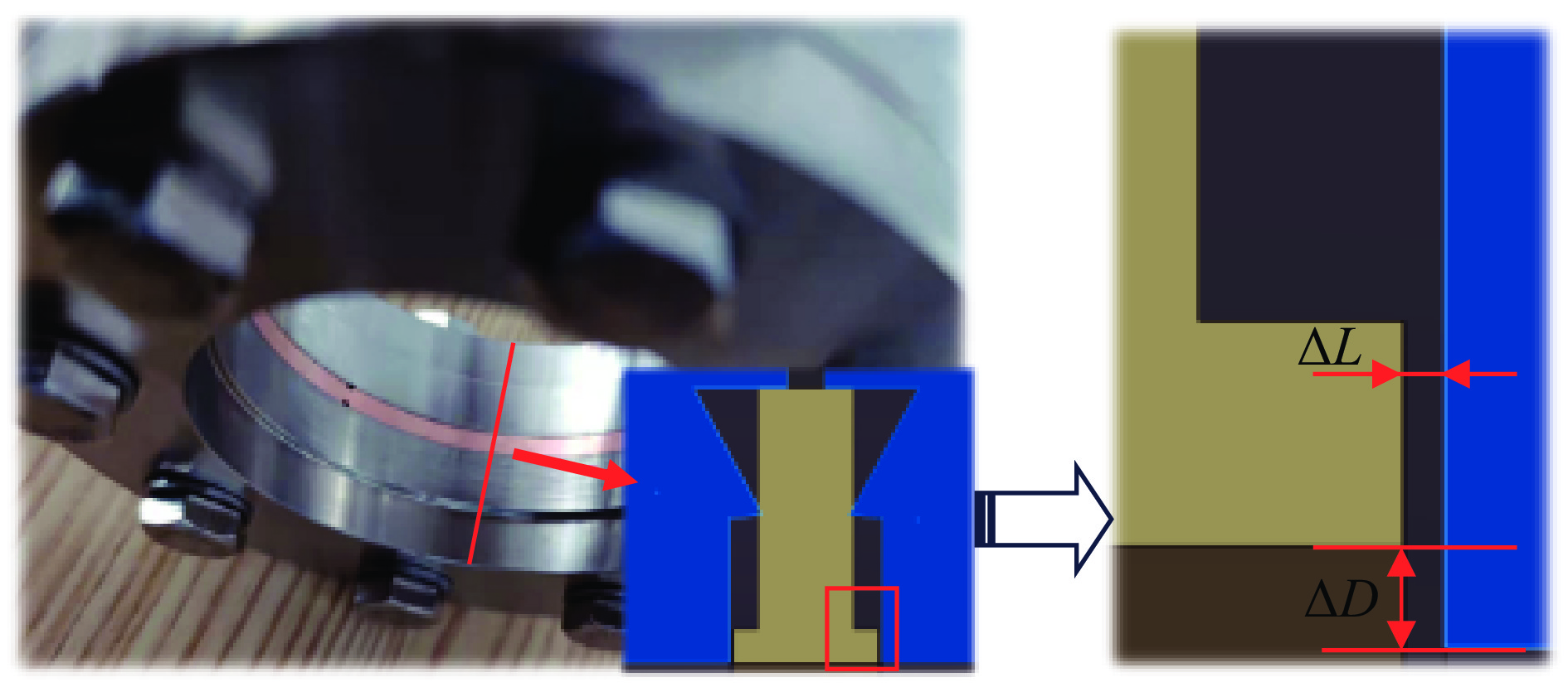
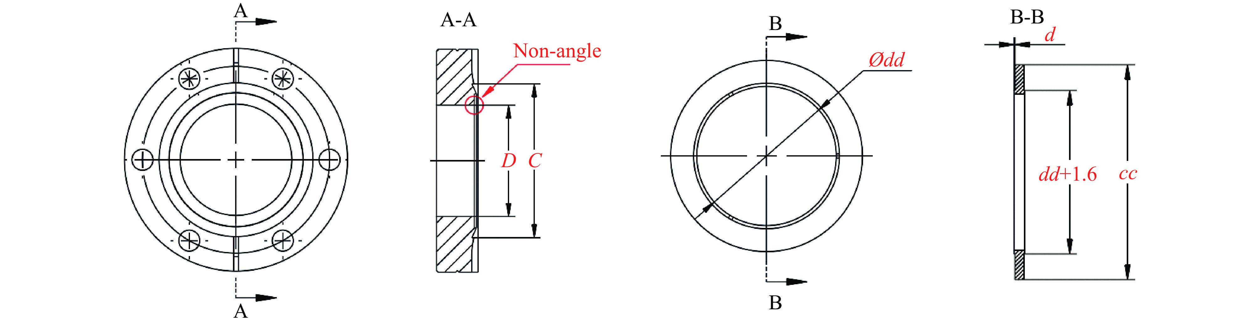
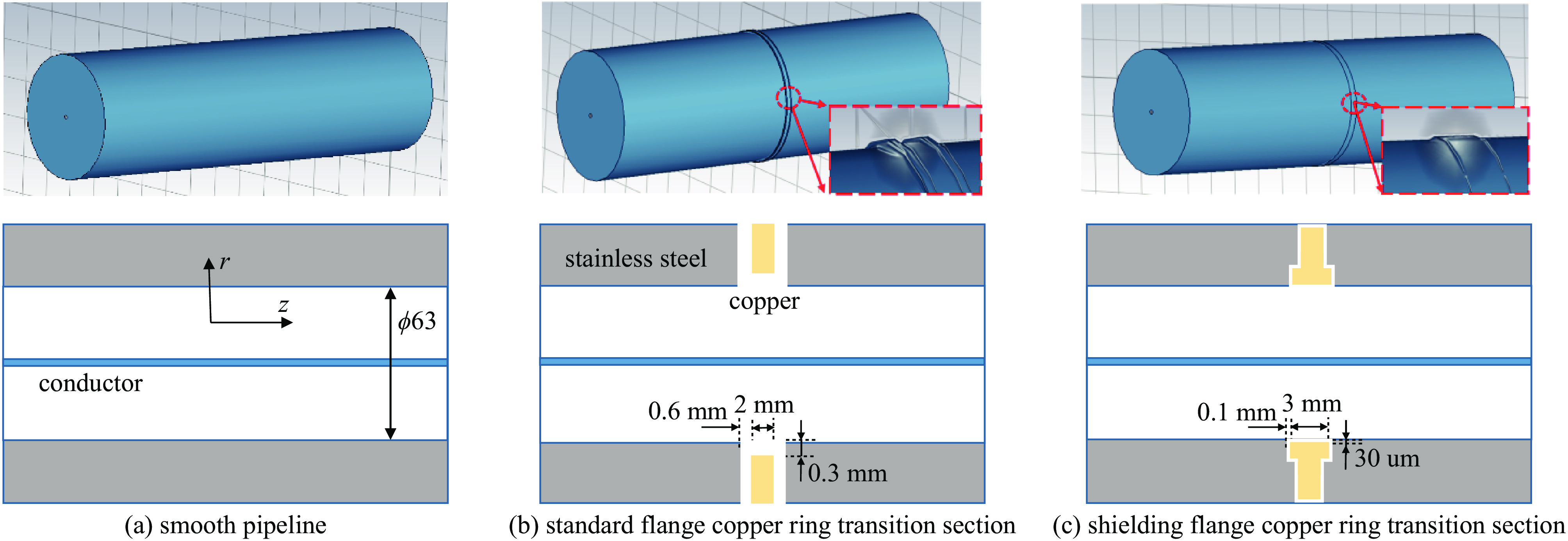
图 1 法兰铜圈连接过渡段示意图
Figure 1. Schematic diagram of the transition section of the flange copper ring connection
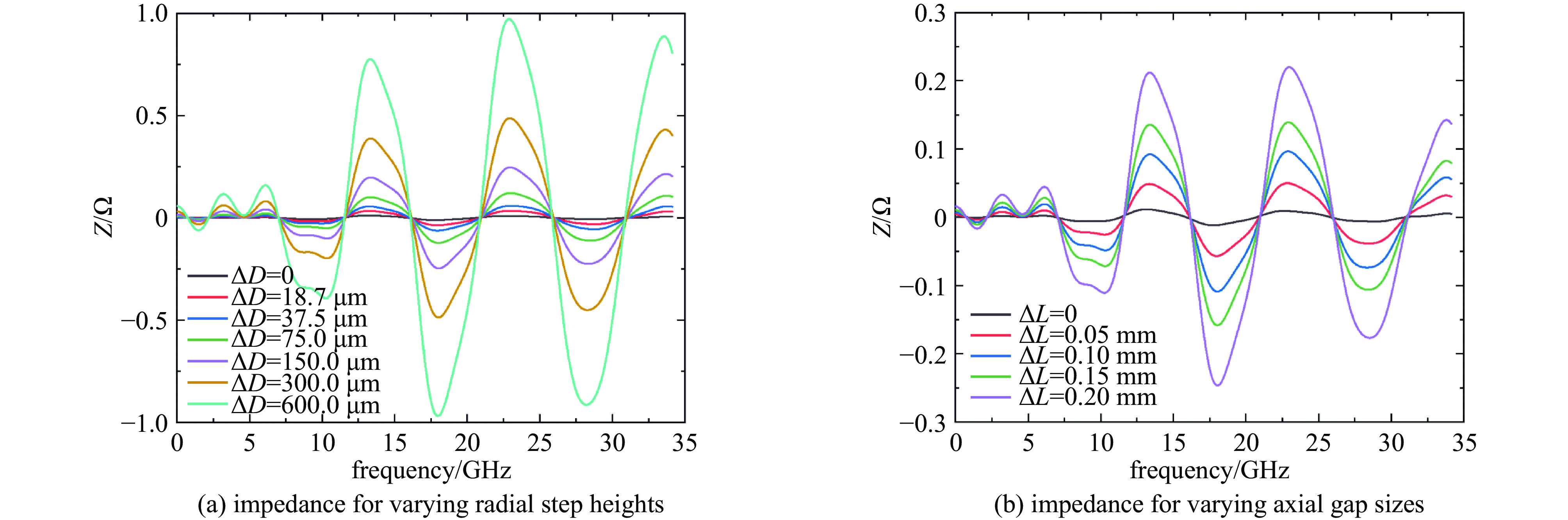
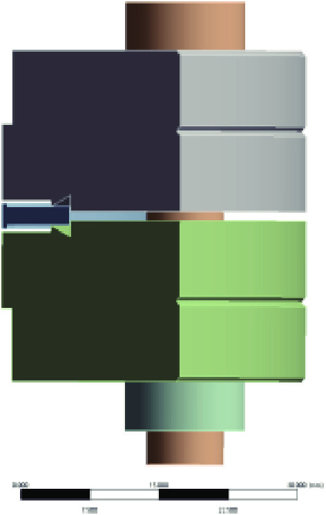
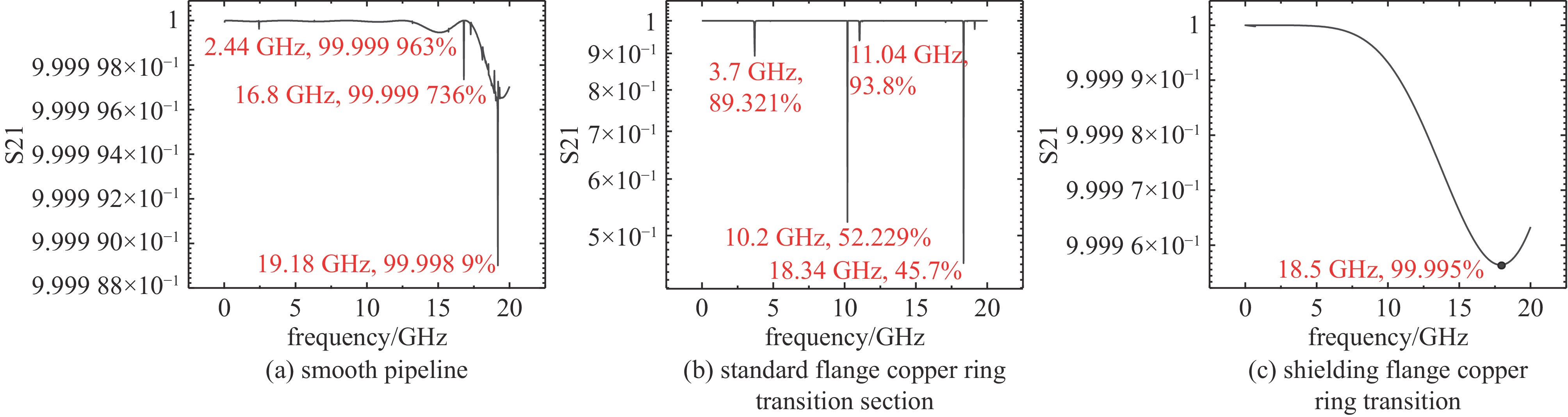
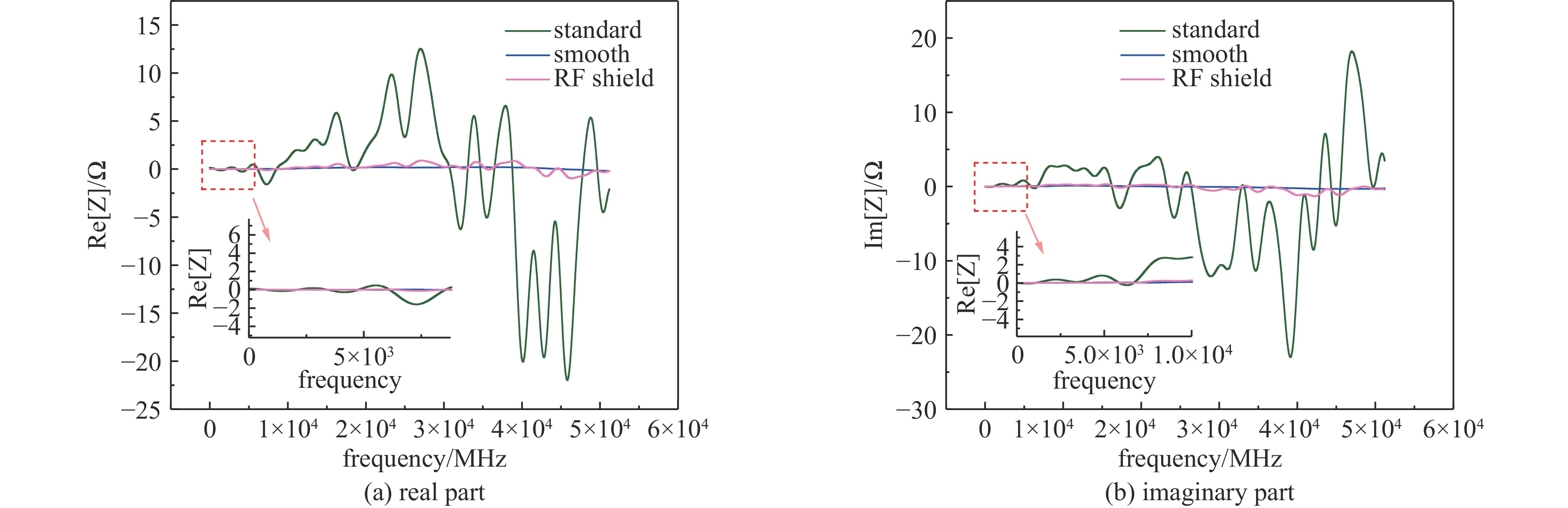
图 2 法兰铜圈连接过渡段射频阻抗仿真
Figure 2. RF Impedance Simulation of Vacuum Flange Transition with Copper Gasket
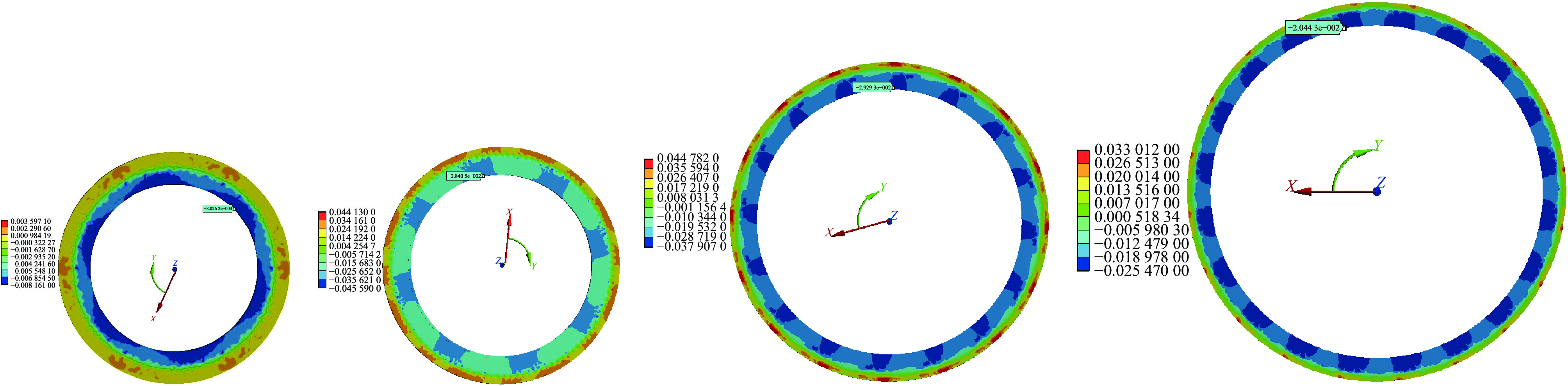
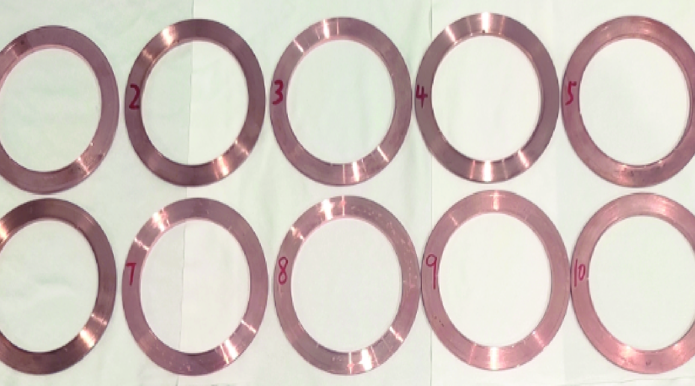
图 5 不同型号的屏蔽铜圈塑性变形仿真结果
Figure 5. Simulation results of plastic deformation of different types of shielded copper ring
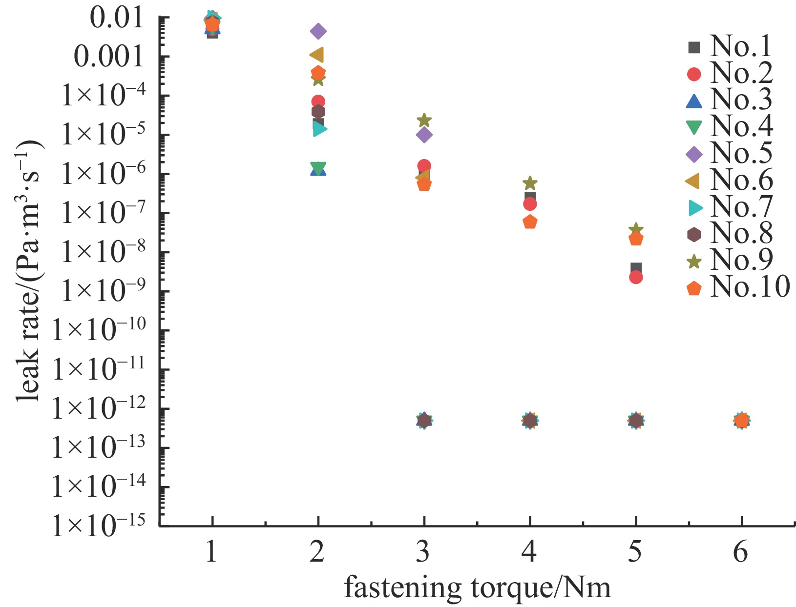
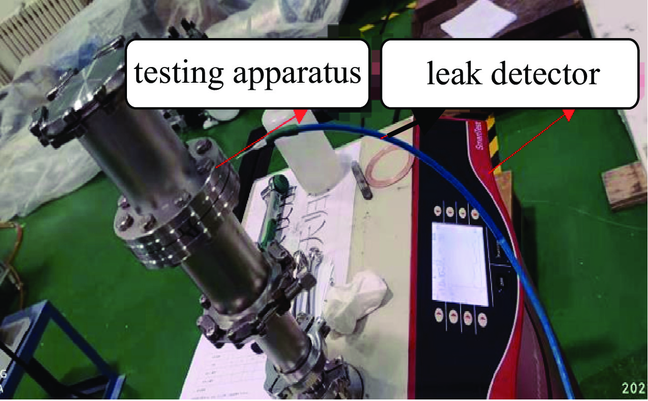
图 9 不同预紧力矩下装置漏率结果
Figure 9. Leakage rate of the device under different fastening torques
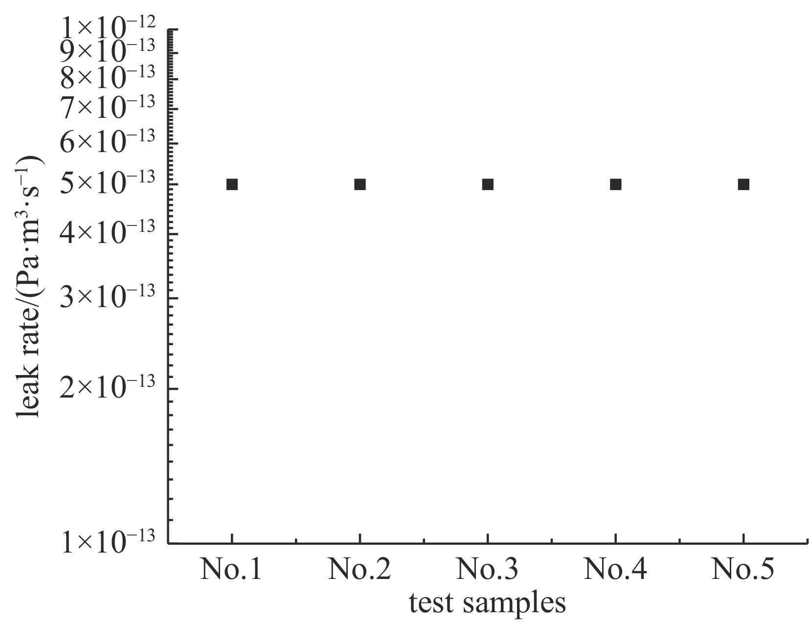
图 10 高温烘烤后装置漏率检测结果
Figure 10. Leakage rate of the device after high temperature baking
表 1 不同型号屏蔽铜圈内外径加工尺寸
Table 1. Different types of shielded copper inner diameter and outer diameter processing size
types DN35 DN50 DN63 DN100 internal diameter /mm 350.020.04 500.040.06 630.060.08 1000.080.16 external diameter /mm 48.3-0.0110 61.6-0.0130 82.5-0.0150 120.6-0.0180  下载: 导出CSV
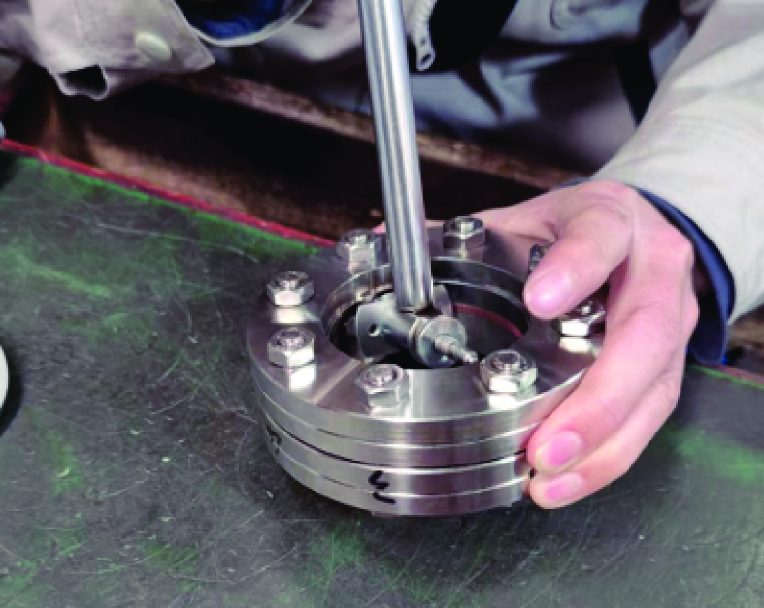
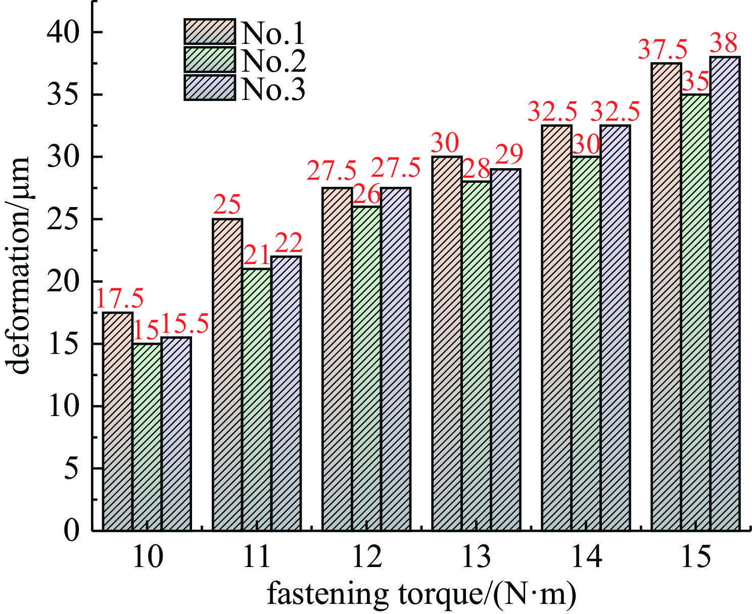
表 2 屏蔽法兰-密封圈连接过渡段径向台阶高度
Table 2. The height of the radial steps of the copper ring flange connection transition section
moment /N·m 10 11 12 13 14 15 16 ΔD/um sample 1 −58 −40 −30 −15 −5 10 20 sample 2 −50 −43 −38 −25 −10 5 0 sample 3 −55 −37 −29 −10 −0 5 10 sample 4 −56 −40 −30 −15 −5 10 20 sample 5 −58 −39 30 −10 −0 9 15
下载: 导出CSV
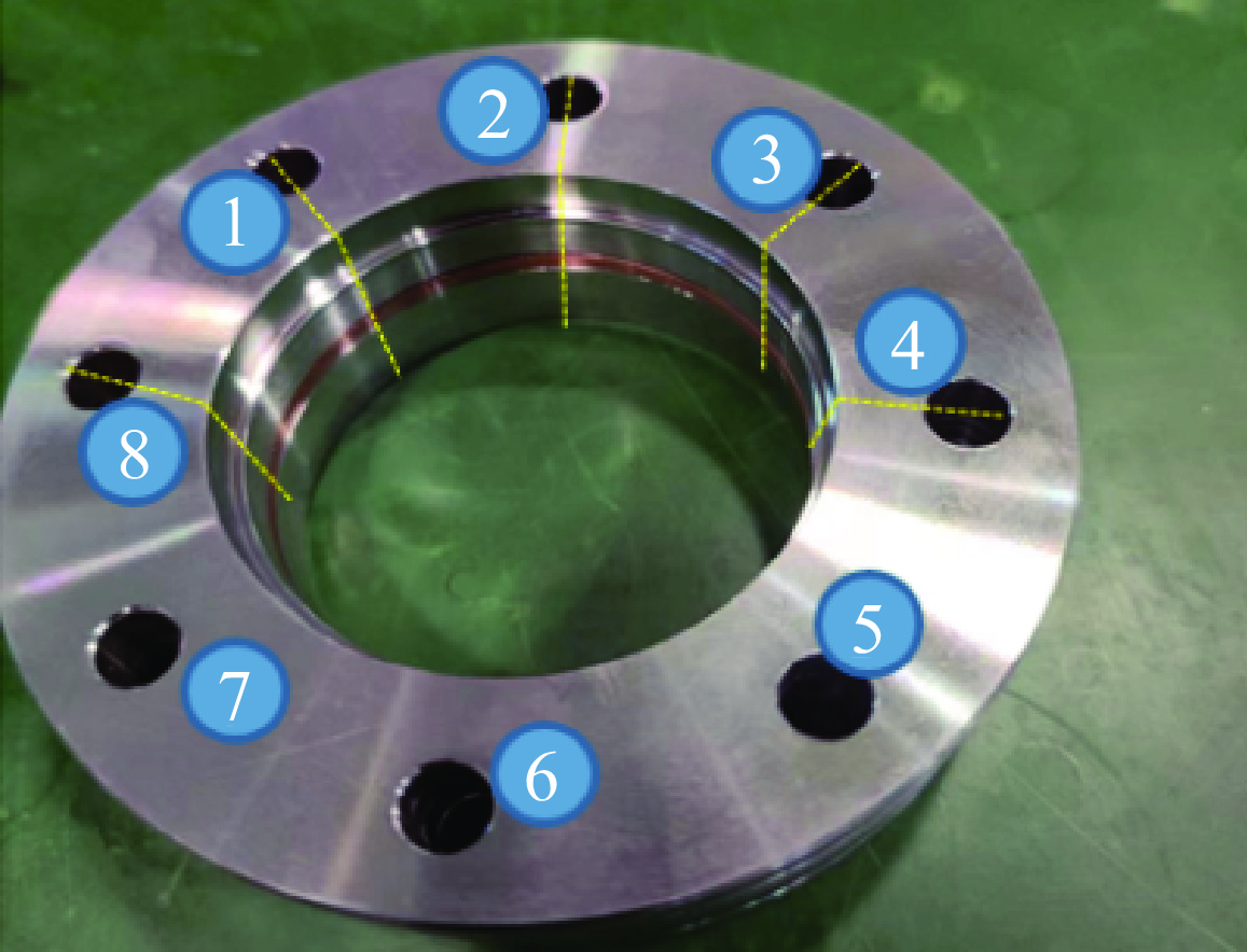
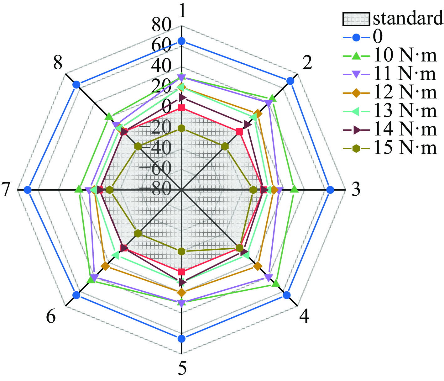
表 3 铜圈法兰连接过渡段轴向间隙
Table 3. The copper ring flange connects the axial clearance of the transition section
position 1/mm 2/mm 3/mm 4/mm 5/mm 6/mm 7/mm 8/mm Step height 0.4 mm Screw side 0.2 0.2 0.2 0.18 0.18 0.18 0.2 0.2 Nut side 0.17 0.18 0.19 0.2 0.18 0.18 0.18 0.17 Step height 0.45 mm Screw side 0.15 0.14 0.13 0.13 0.13 0.14 0.16 0.16 Nut side 0.16 0.17 0.16 0.19 0.18 0.18 0.18 0.18 Step height 0.5 mm Screw side 0.1 0.09 0.062 0.058 0.068 0.068 0.096 0.1 Nut side 0.084 0.088 0.088 0.118 0.118 0.118 0.11 0.09
下载: 导出CSV
-
[1] Chao A. Beam dynamics of collective instabilities in high-energy accelerators[C]//Proceedings of the CAS-CERN Accelerator School: Intensity Limitations in Particle Beam. 2017: 43-43. [2] Dohlus M, Wanzenberg R. An introduction to wake fields and impedances[C]//Proceedings of the CAS-CERN Accelerator School on Intensity Limitations in Particle Beams. 2017: 15. [3] Davtyan A, Isunts H, Dekhtiarov V, et al. The analysis and experimental research of ultrahigh vacuum ConFlat-type flange joints applied in accelerator and space technology[J]. Journal of Instrumentation, 2023, 18: P03013. doi: 10.1088/1748-0221/18/03/P03013 [4] Schroer C G, Falkenberg C. Hard X-ray nanofocusing at low-emittance synchrotron radiation sources[J]. Journal of Synchrotron Radiation, 2014, 21: 996-1005. doi: 10.1107/S1600577514016269 [5] Suetsugu Y, Shirai M, Ohtsuka M. Application of a Matsumoto-Ohtsuka-type vacuum flange to beam ducts for future accelerators[J]. Journal of Vacuum Science & Technology A, 2005, 23(6): 1721-1727. [6] Suetsugu Y, Shirai M, Ohtsuka M, et al. Development of copper-alloy Matsumoto–Ohtsuka-type vacuum flanges and its application to accelerator beam pipes[J]. Journal of Vacuum Science & Technology A, 2009, 27(6): 1303-1309. [7] Heifets S A, Kheifets S A. Coupling impedance in modern accelerators[J]. Reviews of Modern Physics, 1991, 63(3): 631-673. doi: 10.1103/RevModPhys.63.631 [8] Migliorati M, Palumbo L, Zannini C, et al. Resistive wall impedance in elliptical multilayer vacuum chambers[J]. Physical Review Accelerators and Beams, 2019, 22: 121001. doi: 10.1103/PhysRevAccelBeams.22.121001 [9] Bian Baoyuan, Hong Yuanzhi, Wang Sihui, et al. Experimental research on the longitudinal coupling impedance of RF-shielded BPM-bellows assemblies designed for the Hefei Advanced Light Facility[J]. Nuclear Instruments and Methods in Physics Research Section A: Accelerators, Spectrometers, Detectors and Associated Equipment, 2022, 1042: 167450. doi: 10.1016/j.nima.2022.167450 [10] Suetsugu Y, Ohshima K, Kanazawa K. Design studies on a vacuum bellows assembly with radio frequency shield for the KEK B factory[J]. Review of Scientific Instruments, 1996, 67(8): 2796-2811. doi: 10.1063/1.1147110 [11] Suetsugu Y, Shirai M, Ohtsuka M. Application of stainless-steel, copper-alloy and aluminum-alloy MO (Matsumoto-Ohtsuka)-type flanges to accelerator beam pipes[C]//Proceedings of the 1st International Particle Accelerator Conference. 2010: 3855-3857. [12] Huttel E. Materials for accelerator vacuum systems[R]. Snekersten: CERN, 1999: 237-255. [13] Virostek S, Hoff M, Li D, et al. Mechanical design & analysis of a 200 MHz, bolt-together RFQ for the accelerator driven neutron source[C]//Proceedings of the 2007 IEEE Particle Accelerator Conference (PAC). 2007: 2313-2315. [14] Chen Z, Gautier C, Hemez F, et al. Vacuum seals design and testing for a linear accelerator of the National Spallation Neutron Source[R]. Los Alamos: Los Alamos National Laboratory, 2000. [15] Wegman R F, Van Twisk J. Copper and copper alloys[M]//Wegman R F, Van Twisk J. Surface Preparation Techniques for Adhesive Bonding. 2nd ed. Boston: William Andrew, 2013: 83-91. [16] Dylla H F, Biallas G, Dillon-Townes L A, et al. Design and installation of a low particulate, ultrahigh vacuum system for a high power free-electron laser[J]. Journal of Vacuum Science & Technology A, 1999, 17(4): 2113-2118. [17] Mapes M, Smart L, Weiss D, et al. Energy recovery linac: vacuum[R]. New York: Brookhaven National Laboratory (BNL), 2010. [18] Wei J. Synchrotrons and accumulators for high intensity protons: issues and experiences[R]. New York: Brookhaven National Laboratory (BNL), 2000. [19] Kirbie H, Caporaso G, Goerz D, et al. MHz repetition rate solid-state driver for high current induction accelerators[C]//Proceedings of the 1999 Particle Accelerator Conference. 1999: 625-627. [20] Kennelly A E. Impedance[J]. Transactions of the American Institute of Electrical Engineers, 1893, X: 172-232. [21] Safi D, Birtel P, Meyne S, et al. A traveling-wave tube simulation approach with CST particle studio[J]. IEEE Transactions on Electron Devices, 2018, 65(6): 2257-2263. doi: 10.1109/TED.2018.2798810 -

 点击查看大图
计量
- 文章访问数: 49
- HTML全文浏览量: 23
- PDF下载量: 4
- 被引次数: 0
